SECTION 1 – INSTALLATION
D. Install the discharge adapter. See Figure 1.3.
SECURE WITH |
| INSERT PIN |
| ||
COTTER PIN |
| THRU HOLE |
LIPHOOK
FASTEN HOOK |
|
OVER LIP ON | DISCHARGE |
DECK. PUSH DOWN | |
TO SECURE IN | ADAPTER |
PLACE. | FIGURE 1.3 |
1.3BLADE INSTALLATION - 61” DECKS ONLY NOTE: Blade Part No.
A.Apply parking brake.
B.Use a hydraulic floor jack or hoist to raise machine high enough to gain access to the underside of deck. Secure machine with safety blocks.
D. Use blade hardware previously removed to install new kit blade to
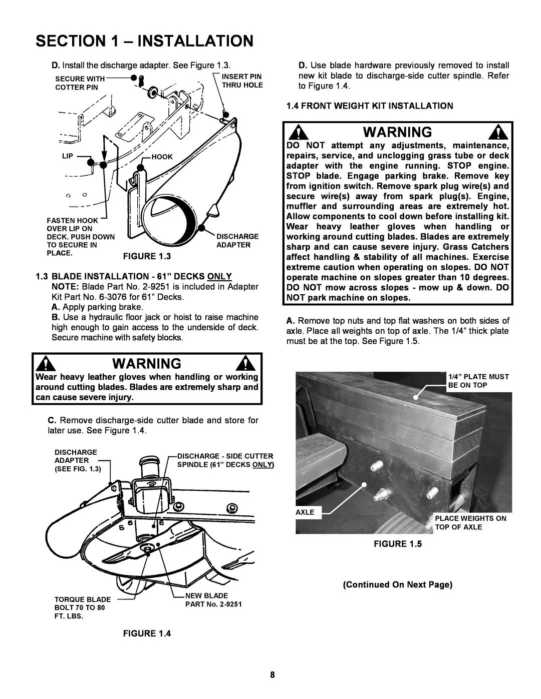
1.4 FRONT WEIGHT KIT INSTALLATION
WARNING
DO NOT attempt any adjustments, maintenance, repairs, service, and unclogging grass tube or deck adapter with the engine running. STOP engine. STOP blade. Engage parking brake. Remove key from ignition switch. Remove spark plug wire(s) and secure wire(s) away from spark plug(s). Engine, muffler and surrounding areas are extremely hot. Allow components to cool down before installing kit. Wear heavy leather gloves when handling or working around cutting blades. Blades are extremely sharp and can cause severe injury. Grass Catchers affect handling & stability of all machines. Exercise extreme caution when operating on slopes. DO NOT operate machine on slopes greater than 10 degrees. DO NOT mow across slopes - mow up & down. DO NOT park machine on slopes.
A. Remove top nuts and top flat washers on both sides of axle. Place all weights on top of axle. The 1/4” thick plate must be at the top. See Figure 1.5.
WARNING
Wear heavy leather gloves when handling or working around cutting blades. Blades are extremely sharp and can cause severe injury.
C. Remove
DISCHARGE | DISCHARGE - SIDE CUTTER | |
ADAPTER | ||
SPINDLE (61” DECKS ONLY) | ||
(SEE FIG. 1.3) | ||
|
1/4” PLATE MUST ![]() BE ON TOP
BE ON TOP
AXLE
PLACE WEIGHTS ON TOP OF AXLE
FIGURE 1.5
(Continued On Next Page)
TORQUE BLADE | NEW BLADE | |
PART No. | ||
BOLT 70 TO 80 | ||
FT. LBS. |
|
FIGURE 1.4
8