Section 4 - ADJUSTMENT & REPAIR
4.4.5. 33" MOWER BLADE REPLACEMENT (Continued)
6.Install new blade, part number
7.Torque 30 to 40 ft lbs.
4.4.6 TRACTION DRIVE BELT REPLACEMENT
It is necessary to remove deck in order to replace belts. Remove deck as follows:
1.Place tractor on a firm, level surface such as a driveway or garage floor and set the park brake.
2.Turn engine “OFF”. Remove key.
3.Lower the deck to lowest setting.
4.Disconnect the deck lift rod from the front lift arm. See Figure 4.23.
FRONT LIFT
ARM
FRONT LIFT
ROD
WASHER
HAIR PIN
FIGURE 4.23
WARNING
DO NOT attempt any adjustments, maintenance or service with the engine or blade running. STOP blade. STOP engine. Set brake. Remove key. Remove spark plug wire from spark plug and secure wire away from spark plug. Engine and components can be extremely hot. Avoid burns by allowing engine and components sufficient time to cool.
4.4.6TRACTION DRIVE BELT REPLACEMENT Mower Deck Removal
5.Remove hair pins from the front deck hanger
rod. See Figure 4.24.
RIGHT
SIDE
SHOWN
FRONT
AXLE
FRONT DECK
HANGER ROD
FRONT LIFT ARM
HAIR PIN
FIGURE 4.24
6.Hold front of deck "UP" and slide the front deck hanger rod to the right and out then lower the front of deck to the ground.
7.Remove hair pin and flat washer from rear deck hanger bracket on both sides of tractor.
8.Make note of hole used in sector plates.
9.Slide sector plates off of rear deck hanger brackets.
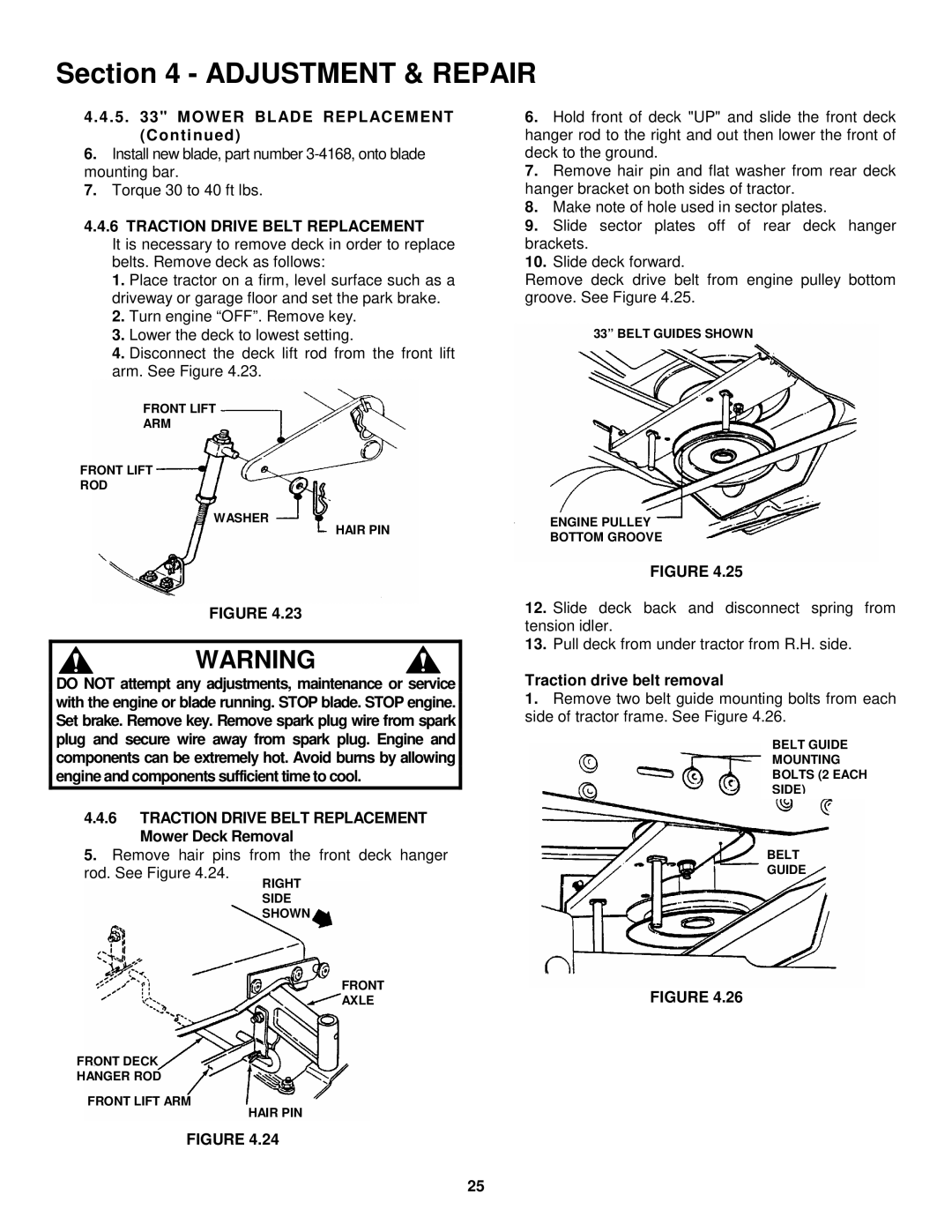
10.Slide deck forward.
Remove deck drive belt from engine pulley bottom groove. See Figure 4.25.
33” BELT GUIDES SHOWN
ENGINE PULLEY
BOTTOM GROOVE
FIGURE 4.25
12.Slide deck back and disconnect spring from tension idler.
13.Pull deck from under tractor from R.H. side.
Traction drive belt removal
1.Remove two belt guide mounting bolts from each side of tractor frame. See Figure 4.26.
BELT GUIDE
MOUNTING
BOLTS (2 EACH
SIDE)
BELT
GUIDE
FIGURE 4.26
25