Section 3 - OPERATING INSTRUCTIONS
3.3CUTTING HEIGHT ADJUSTMENT
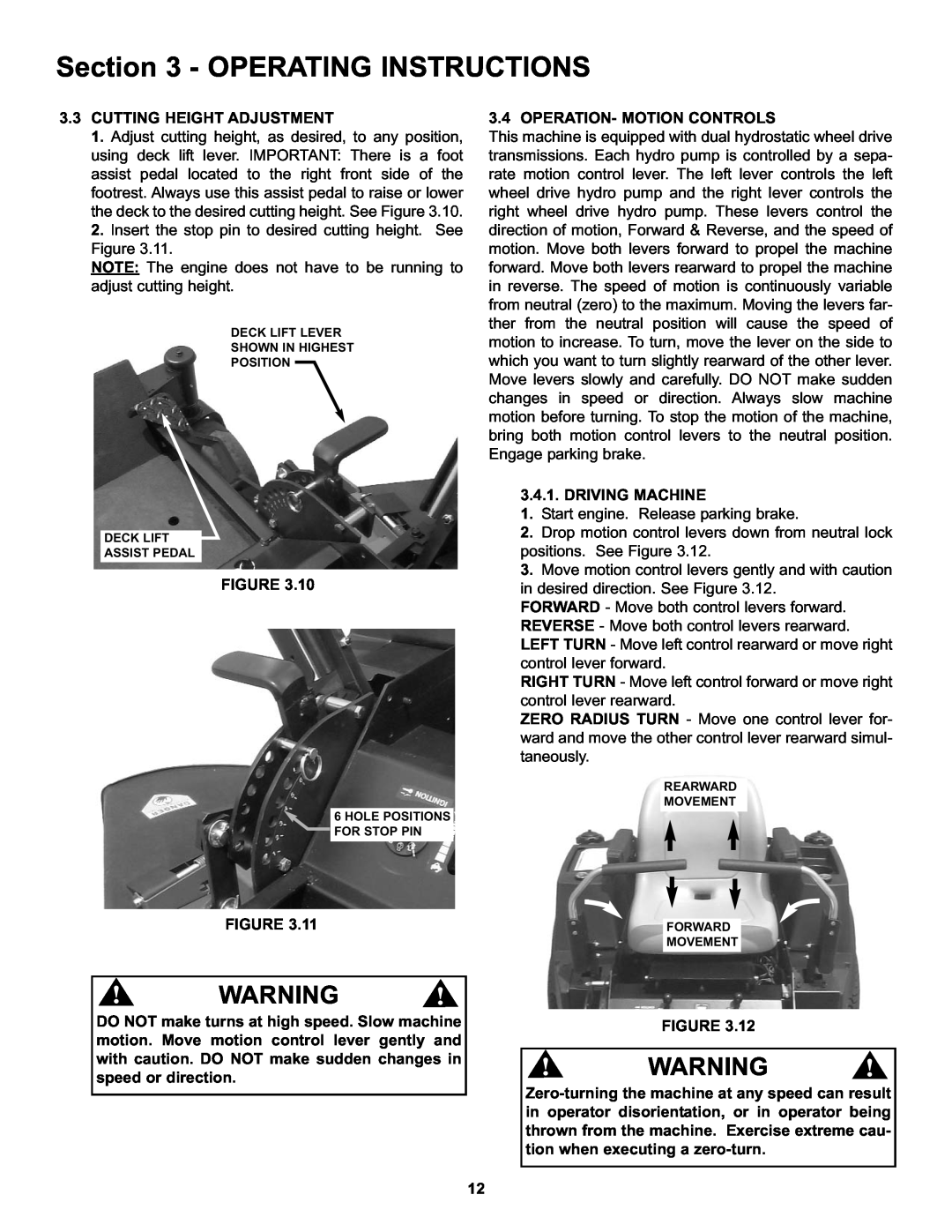
1.Adjust cutting height, as desired, to any position, using deck lift lever. IMPORTANT: There is a foot assist pedal located to the right front side of the footrest. Always use this assist pedal to raise or lower the deck to the desired cutting height. See Figure 3.10.
2.Insert the stop pin to desired cutting height. See Figure 3.11.
NOTE: The engine does not have to be running to adjust cutting height.
DECK LIFT LEVER
SHOWN IN HIGHEST
POSITION
DECK LIFT
ASSIST PEDAL
FIGURE 3.10
6 HOLE POSITIONS FOR STOP PIN
3.4 OPERATION- MOTION CONTROLS
This machine is equipped with dual hydrostatic wheel drive transmissions. Each hydro pump is controlled by a sepa- rate motion control lever. The left lever controls the left wheel drive hydro pump and the right lever controls the right wheel drive hydro pump. These levers control the direction of motion, Forward & Reverse, and the speed of motion. Move both levers forward to propel the machine forward. Move both levers rearward to propel the machine in reverse. The speed of motion is continuously variable from neutral (zero) to the maximum. Moving the levers far- ther from the neutral position will cause the speed of motion to increase. To turn, move the lever on the side to which you want to turn slightly rearward of the other lever. Move levers slowly and carefully. DO NOT make sudden changes in speed or direction. Always slow machine motion before turning. To stop the motion of the machine, bring both motion control levers to the neutral position. Engage parking brake.
3.4.1. DRIVING MACHINE
1.Start engine. Release parking brake.
2.Drop motion control levers down from neutral lock positions. See Figure 3.12.
3.Move motion control levers gently and with caution in desired direction. See Figure 3.12.
FORWARD - Move both control levers forward. REVERSE - Move both control levers rearward. LEFT TURN - Move left control rearward or move right control lever forward.
RIGHT TURN - Move left control forward or move right control lever rearward.
ZERO RADIUS TURN - Move one control lever for- ward and move the other control lever rearward simul- taneously.
REARWARD
MOVEMENT
FIGURE 3.11
! | WARNING | ! |
DO NOT make turns at high speed. Slow machine motion. Move motion control lever gently and with caution. DO NOT make sudden changes in speed or direction.
FORWARD
MOVEMENT
FIGURE 3.12
! | WARNING | ! |
12
