Manuals
/
Snapper
/
Lawn and Garden
/
Lawn Mower
Snapper
HZT21481BV Adjustments & Repair, Mower Deck & Component Adjustments, Figure Figure
Models:
HZT21481BV
1
20
40
40
Download
40 pages
52.05 Kb
17
18
19
20
21
22
23
24
Troubleshooting
Warranty
Maintenance
Battery Condition Chart
3.3CUTTING HEIGHT ADJUSTMENT
5.4TRACTION BELT REPLACEMENT
Safety
Service Schedule
Ignition Switch
Page 20
Image 20
Page 19
Page 21
Page 20
Image 20
Page 19
Page 21
Contents
MID-MOUNT ZERO TURNING HYDRO DRIVE SERIES
Safety Instructions & Operators Manual for
MODELS
HZT21481BV
IMPORTANT SAFETY INSTRUCTIONS
PROTECTION FOR CHILDREN
PROTECTION AGAINST TIPOVERS
PREPARATION
SAFE HANDLING OF GASOLINE
OPERATION
MAINTENANCE
TOWING
TABLE OF CONTENTS
1.2 NOMENCLATURE
Section 1 - FAMILIARIZATION
1.1 INTRODUCTION
Section 2 - SAFETY MESSAGES AND SYMBOLS
CATCHER MUST BE INSTALLED WEAR HEARING PROTECTION
DANGER ! ROTATING PARTS
KEEP AWAY FROM MOVING PARTS
IGNITION SWITCH
CONTROL PANEL IDENTIFICATION
DANGER! ROTATING BLADES
KEEP CHILDREN AND OTHERS OUT OF MOWING AREA
Section 3 - OPERATING INSTRUCTIONS
3.1PRE-STARTCHECK LIST
3.2.1. STARTING ENGINE
3.2.2. STOPPING ENGINE
3.4.1. DRIVING MACHINE
3.3CUTTING HEIGHT ADJUSTMENT
3.4 OPERATION- MOTION CONTROLS
3.4.2. STOPPING MACHINE
Section 4 - MAINTENANCE
4.2SERVICE - AFTER FIRST 5 HOURS
4.1INTRODUCTION
4.2.2. CHECK MOWER BLADE
FIGURE Deck shown with discharge raised
4.3AFTER EVERY 25 OPERATING HOURS 4.3.1. ENGINE
4.3.2.MOWER COMPONENTS 1. Mower Drive Belt
4.4BEFORE OPERATING MACHINE
4.5ANNUALLY END OF EACH SEASON
4.5.1. ENGINE
FIGURE Continued on next Page
4.6DECK REMOVAL
Continued On Next Page
Section 4 - MAINTENANCE
FIGURE Continued On Next Page
Section 5 - ADJUSTMENTS & REPAIR
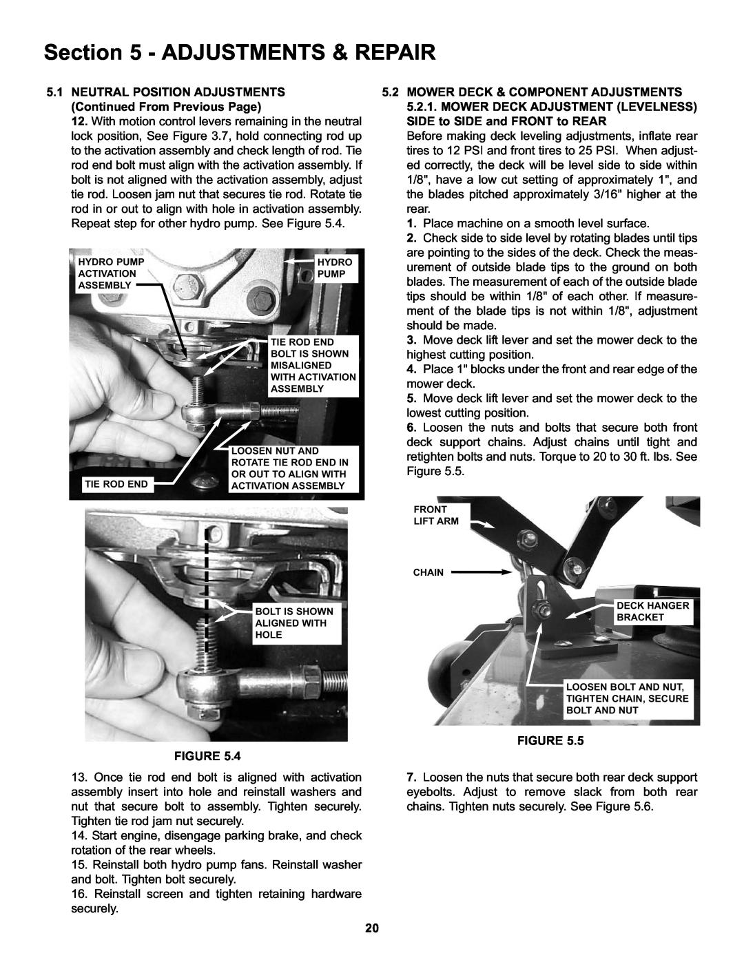
5.1NEUTRAL POSITION ADJUSTMENTS
5.2 MOWER DECK & COMPONENT ADJUSTMENTS
5.2.1. MOWER DECK ADJUSTMENT LEVELNESS
SIDE to SIDE and FRONT to REAR
FIGURE FIGURE
5.3PARKING BRAKE ADJUSTMENT
5.3 TRACTION BELT TENSION
5.4TRACTION BELT REPLACEMENT
FIGURE 5.6TRACKING ADJUSTMENT
5.7.2. BELT REPLACEMENT
5.8ENGINE ADJUSTMENTS & REPAIR
5.9.2. BLADE SHARPENING
5.10BATTERY 5.10.1. BATTERY REMOVAL
Battery Condition Chart
5.11HYDRAULIC SYSTEM, PURGING
TROUBLESHOOTING
PROBLEM
PROBABLE CAUSE
CORRECTIVE ACTION
Battery Will Not Charge
Machine Will Not Move
Loss Of Traction
Blades Not Cutting
SERVICE SCHEDULE
MAINTENANCE/REPLACEMENT PARTS
2 YEAR LIMITED WARRANTY
PRIMARY MAINTENANCE
PRIMARY MAINTENANCE
PRIMARY MAINTENANCE
PRIMARY MAINTENANCE
SNAPPER PRODUCT REGISTRATION FORM
Call the Snapper Customer Relations Center at
Page
Page
Page
Snapper products are built using engines that meet or exceed all applicable emissions requirements on the date manufactured. The labels on those engines contain very important emissions information and critical safety warnings. Read, Understand, and Follow all warnings and instructions in this manual, the engine manual, and on the machine, engine and attachments. If you have any questions about your Snapper product, contact your local authorized Snapper dealer or contact Snapper Customer Service at Snapper, McDonough, GA. 30253. Phone
MANUAL No. 700079 I.R. 5/27/2005
Top
Page
Image
Contents