Section 2 - OPERATING INSTRUCTIONS

2.4ENGINE STARTING PROCEDURE

Step 1: Place the WHEEL and TINE SHIFT LEVER in the NEUTRAL position and make sure the WHEEL and TINE CONTROL BAIL is in the released position.

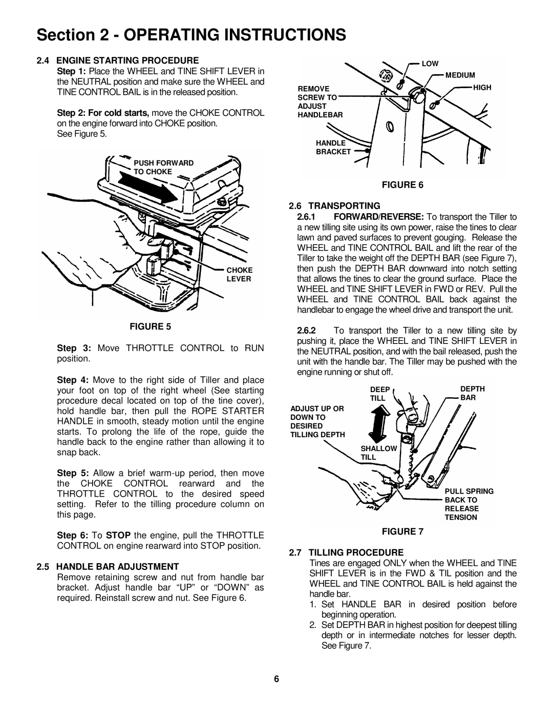
Step 2: For cold starts, move the CHOKE CONTROL on the engine forward into CHOKE position.

See Figure 5.

PUSH FORWARD

TO CHOKE

CHOKE

LEVER

FIGURE 5

Step 3: Move THROTTLE CONTROL to RUN position.

Step 4: Move to the right side of Tiller and place your foot on top of the right wheel (See starting procedure decal located on top of the tine cover), hold handle bar, then pull the ROPE STARTER HANDLE in smooth, steady motion until the engine starts. To prolong the life of the rope, guide the handle back to the engine rather than allowing it to snap back.

Step 5: Allow a brief warm-up period, then move the CHOKE CONTROL rearward and the THROTTLE CONTROL to the desired speed setting. Refer to the tilling procedure column on this page.

Step 6: To STOP the engine, pull the THROTTLE CONTROL on engine rearward into STOP position.

2.5HANDLE BAR ADJUSTMENT

Remove retaining screw and nut from handle bar bracket. Adjust handle bar “UP” or “DOWN” as required. Reinstall screw and nut. See Figure 6.


LOW


MEDIUM


REMOVE

HIGH


SCREW TO


ADJUST


HANDLEBAR


HANDLE


BRACKET


FIGURE 6

2.6TRANSPORTING

2.6.1FORWARD/REVERSE: To transport the Tiller to a new tilling site using its own power, raise the tines to clear lawn and paved surfaces to prevent gouging. Release the WHEEL and TINE CONTROL BAIL and lift the rear of the Tiller to take the weight off the DEPTH BAR (see Figure 7), then push the DEPTH BAR downward into notch setting that allows the tines to clear the ground surface. Place the WHEEL and TINE SHIFT LEVER in FWD or REV. Pull the WHEEL and TINE CONTROL BAIL back against the handlebar to engage the wheel drive and transport the unit.

2.6.2To transport the Tiller to a new tilling site by pushing it, place the WHEEL and TINE SHIFT LEVER in the NEUTRAL position, and with the bail released, push the unit with the handle bar. The Tiller may be pushed with the engine running or shut off.

DEEP

DEPTH

TILL

BAR

ADJUST UP OR

DOWN TO

DESIRED

TILLING DEPTH

SHALLOW

TILL

PULL SPRING

BACK TO

RELEASE

TENSION

FIGURE 7

2.7TILLING PROCEDURE

Tines are engaged ONLY when the WHEEL and TINE SHIFT LEVER is in the FWD & TIL position and the WHEEL and TINE CONTROL BAIL is held against the handle bar.

1.Set HANDLE BAR in desired position before beginning operation.

2.Set DEPTH BAR in highest position for deepest tilling depth or in intermediate notches for lesser depth. See Figure 7.

6

Page 6
Image 6
Snapper IR5003B, NIR5003B Engine Starting Procedure, Handle BAR Adjustment, Transporting, Tilling Procedure

IR5003B, NIR5003B specifications

The Snapper IR5003B and NIR5003B are advanced infrared thermometers that represent the pinnacle of modern temperature measurement technology. These devices have been engineered for precision, durability, and user-friendliness, making them ideal for both professional and amateur applications.

One of the key features of the IR5003B is its laser-guided targeting system. This allows users to accurately measure the temperature of specific surfaces or objects from a distance, ensuring that measurements are taken from exactly the right spot. The dual laser pointers aid in visualizing the measurement area, enhancing accuracy while reducing the chances of error that can occur with wider measurement fields.

The NIR5003B model further extends its capabilities by incorporating advanced non-contact temperature measurement technology. This feature is particularly valuable in applications where direct contact with the subject is not possible or practical, such as moving objects or hazardous materials. Users can obtain quick and accurate temperature readings without the risk of contamination or damage to sensitive surfaces.

Both models boast a wide temperature range, typically spanning from -50°C to 500°C, catering to a variety of use cases, from monitoring food safety to industrial applications. The high-resolution display provides easy visibility of readings, which can be crucial in fast-paced environments where quick decisions are necessary.

Another standout characteristic of the Snapper IR5003B and NIR5003B is their response time. These thermometers are designed to gather data swiftly, allowing users to track temperature changes in real time. This is particularly useful in processes that require consistent monitoring, such as HVAC systems, engine maintenance, and food preparation.

Additionally, these devices offer features like adjustable emissivity settings, enabling users to tailor the device to the properties of different materials for improved accuracy. The ergonomic design ensures that the devices are comfortable to hold and operate, reducing user fatigue during prolonged use.

In summary, the Snapper IR5003B and NIR5003B are versatile infrared thermometers that combine advanced technology and user-friendly features. With laser targeting, non-contact measurement capabilities, a broad temperature range, swift response times, and adjustable emissivity settings, they are designed to meet the demands of various industries efficiently and effectively. Whether for professional use or home applications, these thermometers are invaluable tools for anyone needing precise temperature measurements.