2451-3845, 7/04
MAINTENANCE SECTION BRUSHREPLACEMENT
14.Install new sections by doing the following.
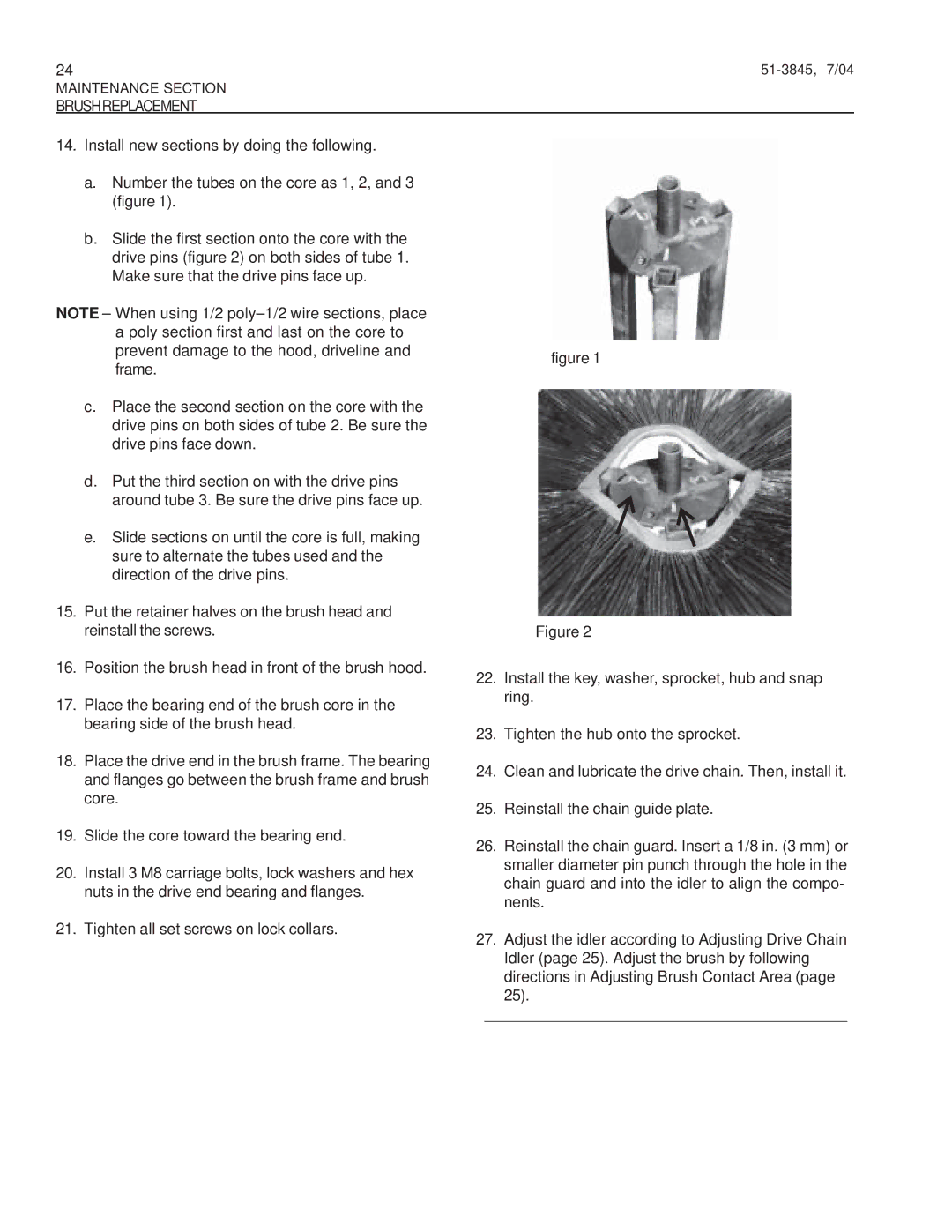
a.Number the tubes on the core as 1, 2, and 3 (figure 1).
b.Slide the first section onto the core with the drive pins (figure 2) on both sides of tube 1. Make sure that the drive pins face up.
NOTE – When using 1/2
c.Place the second section on the core with the drive pins on both sides of tube 2. Be sure the drive pins face down.
d.Put the third section on with the drive pins around tube 3. Be sure the drive pins face up.
e.Slide sections on until the core is full, making sure to alternate the tubes used and the direction of the drive pins.
15.Put the retainer halves on the brush head and reinstall the screws.
16.Position the brush head in front of the brush hood.
17.Place the bearing end of the brush core in the bearing side of the brush head.
18.Place the drive end in the brush frame. The bearing and flanges go between the brush frame and brush core.
19.Slide the core toward the bearing end.
20.Install 3 M8 carriage bolts, lock washers and hex nuts in the drive end bearing and flanges.
21.Tighten all set screws on lock collars.
figure 1
Figure 2
22.Install the key, washer, sprocket, hub and snap ring.
23.Tighten the hub onto the sprocket.
24.Clean and lubricate the drive chain. Then, install it.
25.Reinstall the chain guide plate.
26.Reinstall the chain guard. Insert a 1/8 in. (3 mm) or smaller diameter pin punch through the hole in the chain guard and into the idler to align the compo- nents.
27.Adjust the idler according to Adjusting Drive Chain Idler (page 25). Adjust the brush by following directions in Adjusting Brush Contact Area (page 25).
__________________________________________