Troubleshooting, Adjustments & Service
BRAKE ADJUSTMENT
Brake Adjustment
1.Release the parking brake.
2.Brake arm (C, Figure 25) should be touching stop
(B).
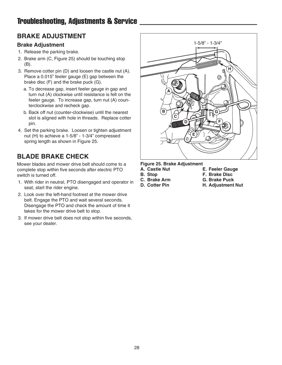
3.Remove cotter pin (D) and loosen the castle nut (A). Place a 0.015” feeler gauge (E) gap between the brake disc (F) and the brake puck (G).
a.To decrease gap, insert feeler gauge in gap and turn nut (A) clockwise until resistance is felt on the feeler gauge. To increase gap, turn nut (A) coun- terclockwise and recheck gap.
b.Back off nut
4.Set the parking brake. Loosen or tighten adjustment nut (H) to achieve a
BLADE BRAKE CHECK
Mower blades and mower drive belt should come to a complete stop within five seconds after electric PTO switch is turned off.
1.With rider in neutral, PTO disengaged and operator in seat, start the rider engine.
2.Look over the
3.If mower drive belt does not stop within five seconds, see your dealer.
| |
| H |
A |
|
B | G |
C |
|
D | F |
| E |
Figure 25. Brake Adjustment
A. Castle Nut | E. Feeler Gauge |
B. Stop | F. Brake Disc |
C. Brake Arm | G. Brake Puck |
D. Cotter Pin | H. Adjustment Nut |
28