SECTION 5 - ADJUSTMENTS
5.3 HANDLE HEIGHT
The operator handle can be adjusted for operator comfort as follows:
1.Loosen the upper carriage bolt and nut on both sides of handlebar. See Figure 5.4.
2.Remove lower carriage bolt and nut on both sides of handlebar.
3.Raise or lower handlebar to desired height. See Figure 5.3.
4.Install the carriage bolt and nut in the lower hole in handlebar and securely tighten nut. See Figure 5.4.
5.Securely tighten the upper carriage bolt and nut.
6.After adjusting the handle height readjust traction links as described earlier. Shift rod (Connects the
ground speed control lever and the transmission) will have to be readjusted.
7.Readjust traction levers/rods when handle height is changed.
*FACTORY SETTINGU
't,
(3)%-
(1)
FIGURE 5.3
RAISE
LOOSEN
UPPER
CARRIAGE
BOLT
LOWER
REMOVE
LOWER
CARRIAGE
BOLT
5.4 TRANSMISSION SHIFT LEVER
ADJUSTMENT
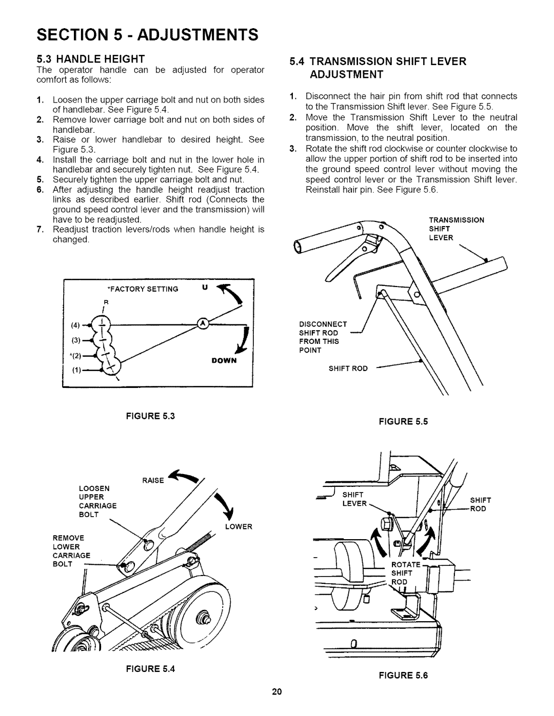
1.Disconnect the hair pin from shift rod that connects
to the Transmission Shift lever. See Figure 5.5.
2, Move the Transmission Shift Lever to the neutral
position. Move the shift lever, located on the transmission, to the neutral position.
3.Rotate the shift rod clockwise or counter clockwise to allow the upper portion of shift rod to be inserted into the ground speed control lever without moving the speed control lever or the Transmission Shift lever. Reinstall hair pin. See Figure 5.6.
TRANSMISSION
SHIFT
LEVER
DISCONNECT
SHIFT ROD
FROM THIS
POINT
SHIFT ROD
FIGURE 5.5
SHIFT
SHIFT
FIGURE 5.4
FIGURE 5.6
20