SECTION 5 - ADJUSTMENTS
5.1STEERING/BRAKES
If machine is not as responsive as desired when either Traction Lever is squeezed, one or both brakes should be adjusted as follows:
1.Operate mower on level terrain with Transmission Shift Lever in No. 1 position. Determine which brake requires adjustment.
2.Stop engine, remove the key from switch and disconnect spark plug wire from spark plug. Secure wire away from plug.
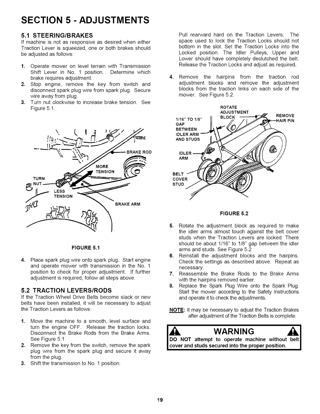
3.Turn nut clockwise to increase brake tension. See Figure 5.1.
'1 \" | (_ | 1 |
TENSION
TORN
BRAKE ARM
FIGURE 5.1
4, Place spark plug wire onto spark plug. Start engine and operate mower with transmission in the No. 1 position to check for proper adjustment. If further adjustment is required, follow all steps above.
5.2 TRACTION LEVERS/RODS
If the Traction Wheel Drive Belts become slack or new
belts have been installed, it will be necessary to adjust the Traction Levers as follows:
1.Move the machine to a smooth, level surface and
turn the engine OFF. Release the traction locks. Disconnect the Brake Rods from the Brake Arms.
See Figure 5.1
2.Remove the key from the switch, remove the spark plug wire from the spark plug and secure it away from the plug.
3.Shift the transmission to No. 1 position.
Pull rearward hard on the Traction Levers. The
space used to lock the Traction Locks should not bottom in the slot. Set the Traction Locks into the
Locked position. The Idler Pulleys, Upper and Lower should have completely declutched the belt. Release the Traction Locks and adjust as required.
4, Remove the hairpins from the traction rod adjustment blocks and remove the adjustment blocks from the traction links on each side of the
mower. See Figure 5.2.
ROTATE
ADJUSTMENT
1/16" TO | 1/8' tj | BLOCK | REMOVE |
GAP | .._ | ,__H | AIRPIN |
BETWEEN |
|
|
|
FIGURE 5.2
5.Rotate the adjustment block as required to make the idler arms almost touch against the belt cover studs when the Traction Levers are locked. There
should be about 1/16" to 1/8" gap between the idler arms and studs. See Figure 5.2
6.Reinstall the adjustment blocks and the hairpins. Check the settings as described above. Repeat as necessary.
7.Reassemble the Brake Rods to the Brake Arms with the hairpins removed earlier.
8.Replace the Spark Plug Wire onto the Spark Plug. Start the mower according to the Safety Instructions and operate it to check the adjustments.
NOTE: It may be necessary to adjust the Traction Brakes after adjustment of the Traction Belts is complete.
Iuo.NOTdoattempt WARNINGto | belt I |
operate machine without | I |
studs secured into the proper position, |
19