Architectural Series™
BPS - 1 I N - C E I L I N G S U B W O O F E R
I N S T A L L A T I O N M A N U A L
Installing the BPS-1 Cabinet In New Construction
WARNING
DO NOT ATTACH THE BPS - 1 TO AN I - JOIST THAT HAS NOT BEEN ADEQUATELY BRACED . DOING SO CAN CAUSE COLLAPSE, RESULTING IN INJURY OR DEATH . CONSULT WITH THE JOB’S GENERAL CONTRACTOR BEFORE ATTACHING THE BPS - 1 TO AN I - JOIST.
1. Determine the location for the
Architectural Series Panel Bracket/Grille and install it according to its instruction manual.
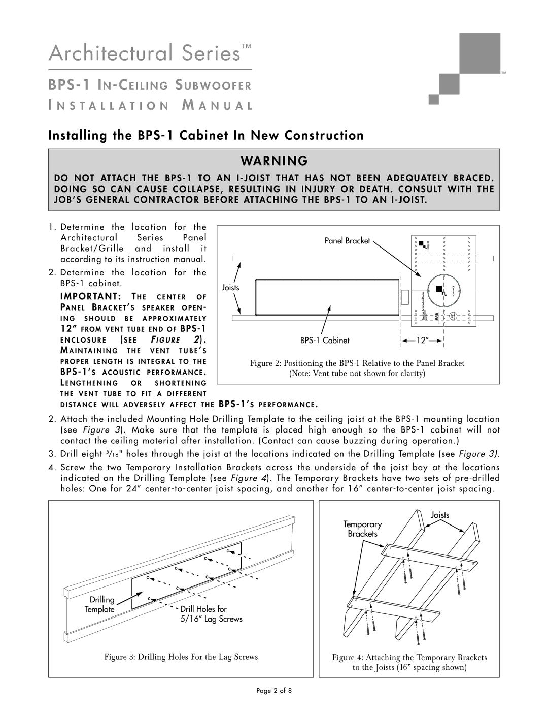
2. Determine the location for the
I M P O RTA N T : T H E | C E N T E R | O F |
PA N E L B R A C K E T ’ S S P E A K E R O P E N - | ||
I N G S H O U L D B E A P P R O X I M A T E L Y | ||
12” F R O M V E N T T U B E E N D O F | ||
E N C L O S U R E ( S E E | F I G U R E | 2 ) . |
M A I N T A I N I N G T H E V E N T T U B E ’ S | ||
Panel Bracket
Joists
BPS-1 Cabinet
|
|
|
|
|
|
|
|
|
SonanceArchitectural Series |
| WWW.SONANCE.COM 800.582.7777 |
|
|
|
|
|
|
|
|
|
|
| ||||
| B6R |
|
|
| 5/8” DRYWALL | |||
|
|
| ||||||
|
|
|
|
|
|
|
|
|
![]() 12”
12”![]()
P R O P E R L E N G T H I S I N T E G R A L T O T H E | |
BPS - 1’ S A C O U S T I C | P E R F O R M A N C E . |
L E N G T H E N I N G O R | S H O R T E N I N G |
T H E V E N T T U B E T O F I T A D I F F E R E N T D I S TA N C E W I L L A D V E R S E L Y A F F E C T T H E
Figure 2: Positioning the BPS-1 Relative to the Panel Bracket
(Note: Vent tube not shown for clarity)
BPS - 1’ S P E R F O R M A N C E .
2. Attach the included Mounting Hole Drilling Template to the ceiling joist at the
3. Drill eight 5/16" holes through the joist at the locations indicated on the Drilling Template (see Figure 3).
4. Screw the two Temporary Installation Brackets across the underside of the joist bay at the locations indicated on the Drilling Template (see Figure 4). The Temporary Brackets have two sets of
Drilling | Drill Holes for |
Template | |
| 5/16” Lag Screws |
Figure 3: Drilling Holes For the Lag Screws | |
Joists
Temporary
Brackets
Figure 4: Attaching the Temporary Brackets
to the Joists (16” spacing shown)
Page 2 of 8