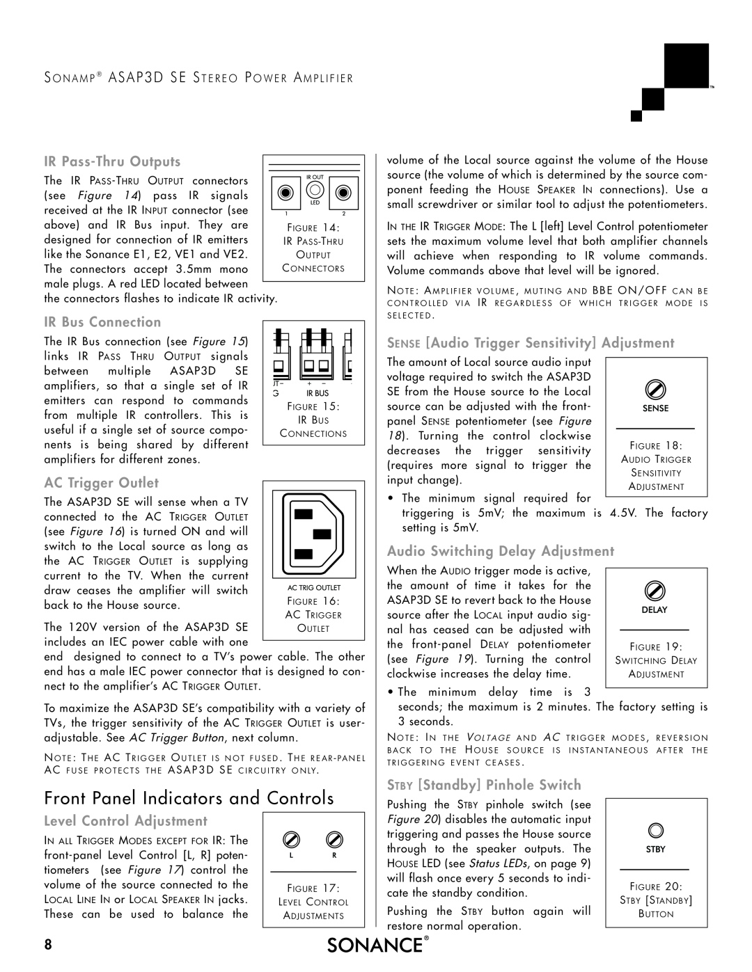
ASAP3D, Sonamp ASAP3D SE Stereo Power Amplifier specifications
Sonance ASAP3D is a cutting-edge software solution designed to streamline 3D modeling and rendering processes for architects, designers, and engineers. This innovative tool integrates advanced features and technologies to enhance productivity and creativity, making it a preferred choice for professionals in various industries.One of the standout features of Sonance ASAP3D is its intuitive user interface, which simplifies the design process even for those with limited 3D modeling experience. The drag-and-drop functionality allows users to easily import and manipulate objects, enabling quick alterations and adjustments to designs. Additionally, the software supports a wide range of file formats, facilitating seamless integration with other design software and tools.
The built-in rendering engine is another significant aspect of Sonance ASAP3D. This high-performance engine allows users to create photorealistic images and animations of their projects, showcasing designs in an appealing and professional manner. With real-time rendering capabilities, designers can visualize changes instantly, which aids in decision-making and collaboration with clients and stakeholders.
Sonance ASAP3D is equipped with powerful modeling tools that provide precision and flexibility. Users can create complex geometries with ease, utilizing features such as parametric modeling, enabling them to define relationships between different design elements. This level of control ensures that changes made to one part of the model automatically update related components, enhancing efficiency.
Collaboration is further enhanced through the software's cloud-based capabilities. Teams can work together in real time, regardless of their physical locations. This feature is particularly beneficial for large projects involving multiple stakeholders, as it fosters effective communication and minimizes the chances of misalignment.
Another essential characteristic of Sonance ASAP3D is its extensive library of pre-built components and materials. Users can access a rich collection of textures, models, and materials that can be easily applied to their designs. This not only speeds up the modeling process but also enriches the visual quality of the final outputs.
Security is a key consideration in design software, and Sonance ASAP3D addresses this with robust data protection protocols. User projects are encrypted and stored securely in the cloud, ensuring that sensitive information remains confidential.
In summary, Sonance ASAP3D combines an intuitive interface, powerful modeling tools, advanced rendering capabilities, and collaborative features to create a comprehensive 3D design solution. Its focus on efficiency, accuracy, and security makes it a valuable asset for professionals seeking to elevate their design processes and outcomes, ultimately leading to better project delivery and client satisfaction.

