SECTION 2
DISASSEMBLY
2-1. CABINETS
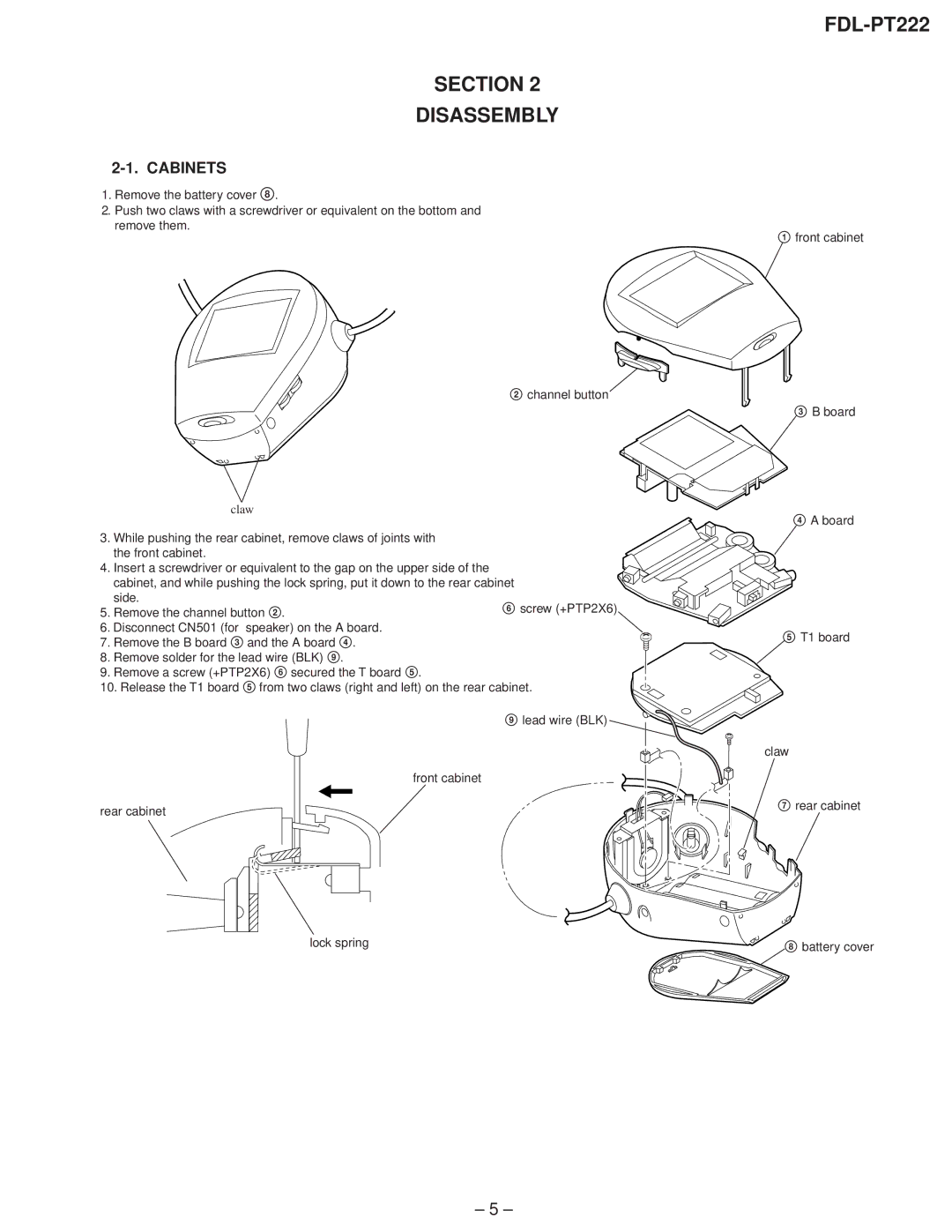
1.Remove the battery cover 8.
2.Push two claws with a screwdriver or equivalent on the bottom and remove them.
2 channel button
claw
3.While pushing the rear cabinet, remove claws of joints with the front cabinet.
4. Insert a screwdriver or equivalent to the gap on the upper side of the cabinet, and while pushing the lock spring, put it down to the rear cabinet
side.
5. Remove the channel button 2.6 screw (+PTP2X6)
6. Disconnect CN501 (for speaker) on the A board.
7. Remove the B board 3 and the A board 4.
8.Remove solder for the lead wire (BLK) 9.
9.Remove a screw (+PTP2X6) 6 secured the T board 5.
10.Release the T1 board 5 from two claws (right and left) on the rear cabinet.
9 lead wire (BLK)
front cabinet
rear cabinet
lock spring
FDL-PT222
1front cabinet
3B board
4A board
5T1 board
claw
7rear cabinet
8battery cover
– 5 –
