Service Manual |
TRANSFORMER, POWER SUPPLY PCB and BACK PLATE ASSEMBLY
NOTE
It is easier to remove the complete TRANSFORMER, POWER SUPPLY PCB and BACK PANEL ASSEMBLY
at the same time, to avoid needless removals.
1. Remove the UPPER HOUSING. See page
2. Remove the CENTER HOUSING. See page
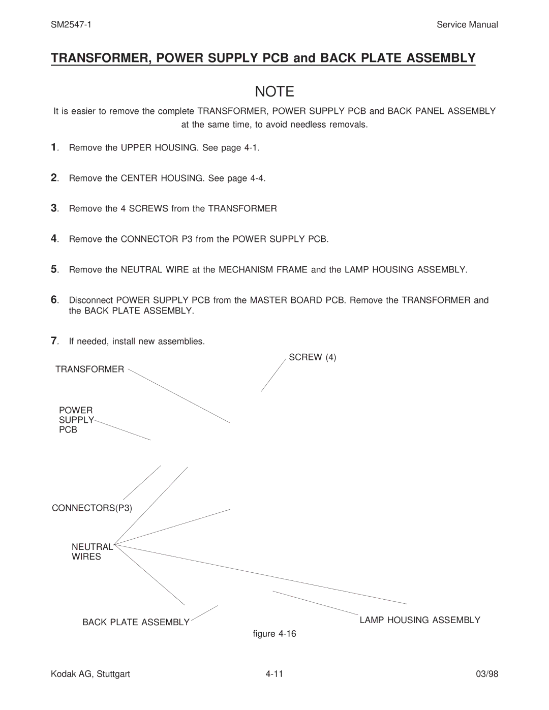
3. Remove the 4 SCREWS from the TRANSFORMER
4. Remove the CONNECTOR P3 from the POWER SUPPLY PCB.
5. Remove the NEUTRAL WIRE at the MECHANISM FRAME and the LAMP HOUSING ASSEMBLY.
6. Disconnect POWER SUPPLY PCB from the MASTER BOARD PCB. Remove the TRANSFORMER and the BACK PLATE ASSEMBLY.
7. If needed, install new assemblies.
SCREW (4)
TRANSFORMER
POWER
SUPPLY
PCB
CONNECTORS(P3)
NEUTRAL
WIRES
BACK PLATE ASSEMBLY | LAMP HOUSING ASSEMBLY |
| figure |
Kodak AG, Stuttgart | 03/98 |