SM | Service Manual |
LAMP Control
a) Dual LAMP Operation
All Models are equipped with a DUAL LAMP MODULE (Extra Bright).
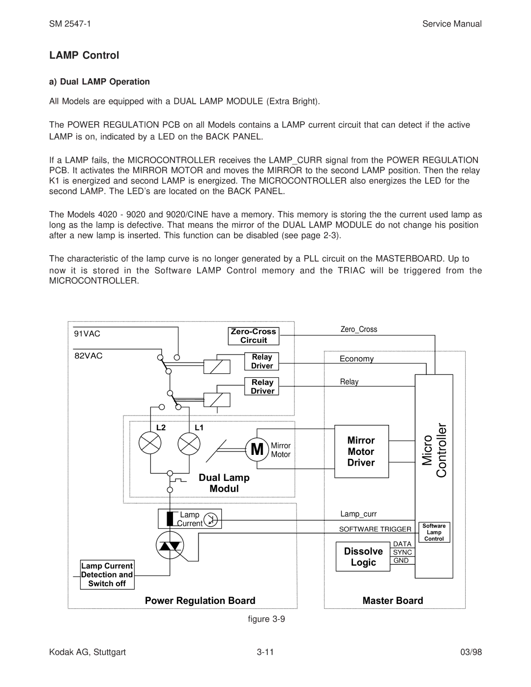
The POWER REGULATION PCB on all Models contains a LAMP current circuit that can detect if the active LAMP is on, indicated by a LED on the BACK PANEL.
If a LAMP fails, the MICROCONTROLLER receives the LAMP_CURR signal from the POWER REGULATION PCB. It activates the MIRROR MOTOR and moves the MIRROR to the second LAMP position. Then the relay K1 is energized and second LAMP is energized. The MICROCONTROLLER also energizes the LED for the second LAMP. The LED’s are located on the BACK PANEL.
The Models 4020 - 9020 and 9020/CINE have a memory. This memory is storing the the current used lamp as long as the lamp is defective. That means the mirror of the DUAL LAMP MODULE do not change his position after a new lamp is inserted. This function can be disabled (see page
The characteristic of the lamp curve is no longer generated by a PLL circuit on the MASTERBOARD. Up to now it is stored in the Software LAMP Control memory and the TRIAC will be triggered from the
MICROCONTROLLER.
91VAC | Zero_Cross |
|
| |
|
|
| ||
Circuit |
|
|
| |
|
|
|
| |
82VAC | Relay | Economy |
|
|
| Driver |
|
|
|
| Relay | Relay |
|
|
| Driver |
|
| Micro Controller |
L2 | L1 |
|
| |
|
|
| ||
| M MirrorMotor | Mirror |
|
|
| Motor |
|
| |
|
| Driver |
|
|
| Dual Lamp |
|
|
|
| Modul |
|
|
|
| Lamp | Lamp_curr |
|
|
| Current | SOFTWARE TRIGGER | Software | |
|
| Lamp | ||
|
|
|
| |
|
|
| DATA | Control |
|
| Dissolve |
| |
|
| SYNC |
| |
Lamp Current |
| Logic | GND |
|
|
|
| ||
|
|
|
| |
Detection and |
|
|
|
|
Switch off |
|
|
|
|
Power Regulation Board | Master Board | |||
| figure |
|
|
|
Kodak AG, Stuttgart | 03/98 |