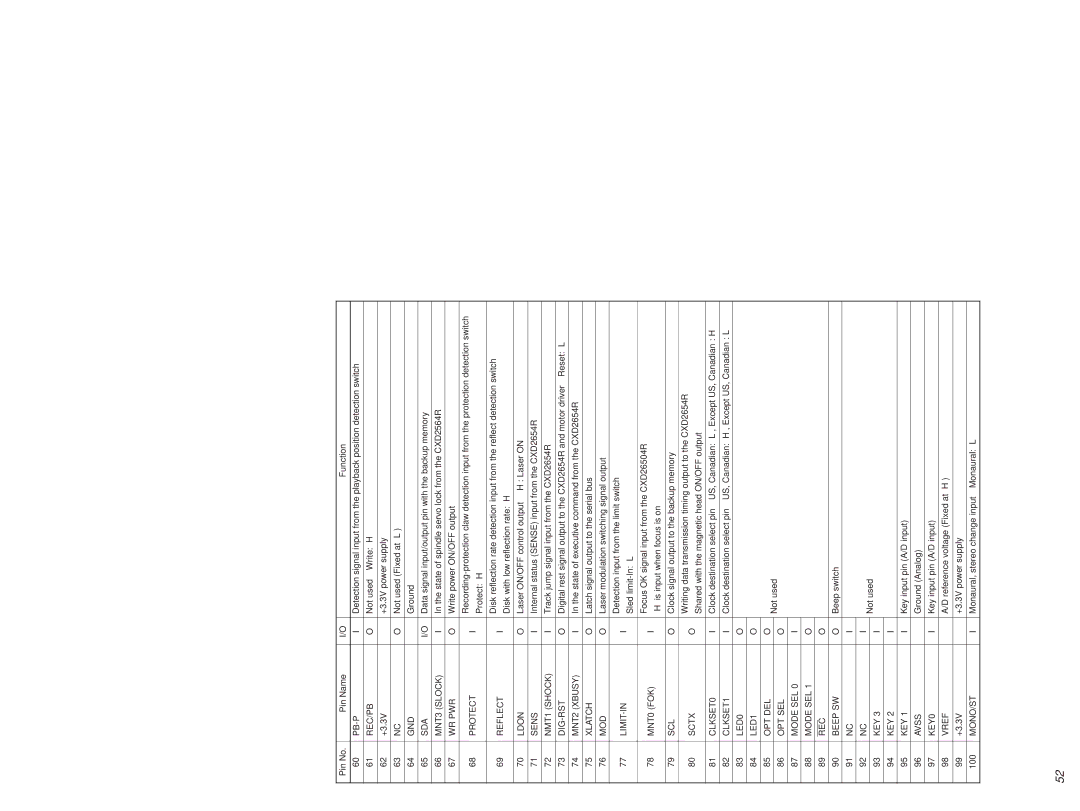
MDS-PC2 specifications
The Sony MDS-PC2 is a compact yet powerful digital MiniDisc recorder that was designed to bring studio-quality recording capabilities to the consumer level. Launched in the late 1990s, this device was particularly notable for its versatility and advanced audio technologies, making it a favorite among audiophiles and home studio enthusiasts alike.One of the standout features of the MDS-PC2 is its ability to record and playback audio with exceptional clarity. It utilizes the MiniDisc format, which employs a magneto-optical technology that allows for higher-quality recordings compared to traditional cassette formats. The MDS-PC2 supports various audio bit rates, including standard Stereo at 292 kbps and long play modes, which double the recording time at the cost of some audio fidelity. This flexibility allows users to tailor their recording settings to their specific needs.
The MDS-PC2 features an intuitive interface, including an easy-to-read LCD display that shows vital information about the track, such as its name, length, and remaining recording time. The device is equipped with multiple input options, including optical and analog connections, facilitating seamless integration into any audio setup. The built-in digital signal processor (DSP) enhances the recording quality by minimizing background noise and distortion, providing a clean and crisp listening experience.
Another notable characteristic is the MDS-PC2's editing capabilities. Users can easily create custom playlists, erase tracks, and rearrange audio sequences with a few simple commands. The unit also supports fade-in and fade-out functionalities, allowing for smooth transitions between tracks. The flexibility in editing makes it a potent tool for podcasters, musicians, and anyone looking to produce high-quality audio content.
Portability is another key aspect of the Sony MDS-PC2. Its lightweight design and durable build make it easy to transport, catering to users who are frequently on the move. Battery operation options provide additional convenience for those who wish to use the recorder away from a power source.
In summary, the Sony MDS-PC2 combines innovative technology with user-friendly features, making it an excellent choice for anyone seeking an efficient and high-quality MiniDisc recorder. Its capability to produce superior audio recordings, coupled with its adaptability and portability, has solidified its place as an essential tool for audio recording and playback in various settings.
