CDX-M620/M670
Inputs | Telephone ATT control | ||
| lead |
|
|
| Illumination control lead | ||
| BUS control input connector | ||
| BUS audio input connector | ||
| Antenna input connector (US model) | ||
| Aerial input connector (AEP, UK, E model) | ||
| AUX IN connector (US model) | ||
Tone controls | Bass ±8 dB at 100 Hz | ||
| Treble ±8 dB at 10 Hz | ||
Loudness | +8 dB at 100 Hz |
| |
| +2 dB at 10 Hz |
|
|
Power requirements | 12 V DC car battery |
| |
| (negative earth) |
| |
Dimensions | Approx. 178 ⋅ | 50 ⋅ | 182 mm |
| (w/h/d) |
|
|
Mounting dimensions | Approx. 182 ⋅ | 53 ⋅ | 160 mm |
| (w/h/d) |
|
|
Mass | Approx. 1.5 kg |
|
|
Supplied accessories | Parts for installation and | ||
| connections (1 set) |
| |
| Front panel case (1) |
| |
Card remote commander
Note
This unit cannot be connected to a digital preamplifier or an equalizer.
Design and specifications are subject to change without notice.
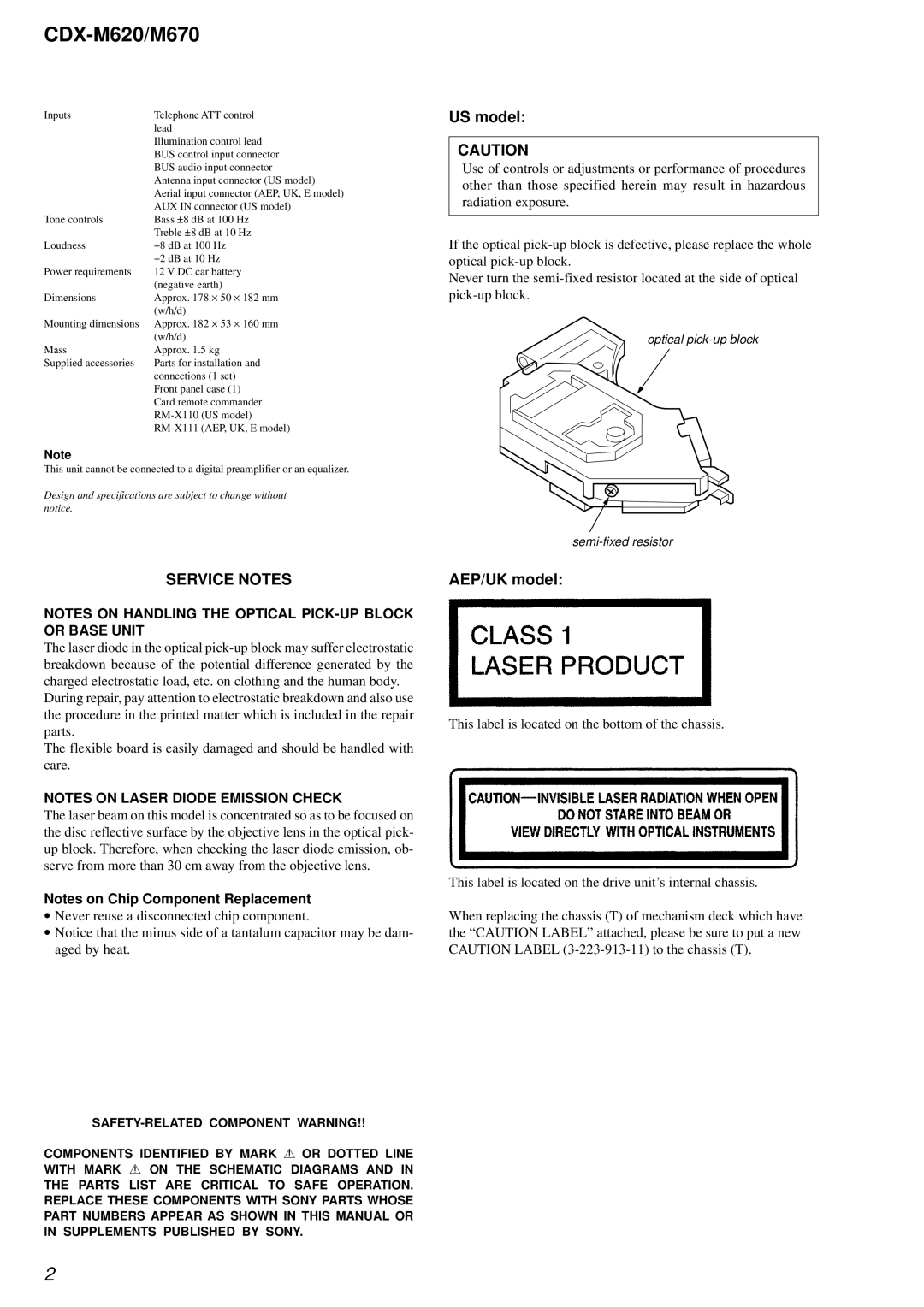
US model:
CAUTION
Use of controls or adjustments or performance of procedures other than those specified herein may result in hazardous radiation exposure.
If the optical
Never turn the
optical
SERVICE NOTES
NOTES ON HANDLING THE OPTICAL
The laser diode in the optical
During repair, pay attention to electrostatic breakdown and also use the procedure in the printed matter which is included in the repair parts.
The flexible board is easily damaged and should be handled with care.
NOTES ON LASER DIODE EMISSION CHECK
The laser beam on this model is concentrated so as to be focused on the disc reflective surface by the objective lens in the optical pick- up block. Therefore, when checking the laser diode emission, ob- serve from more than 30 cm away from the objective lens.
Notes on Chip Component Replacement
•Never reuse a disconnected chip component.
•Notice that the minus side of a tantalum capacitor may be dam- aged by heat.
AEP/UK model:
This label is located on the bottom of the chassis.
This label is located on the drive unit’s internal chassis.
When replacing the chassis (T) of mechanism deck which have the “CAUTION LABEL” attached, please be sure to put a new CAUTION LABEL
COMPONENTS IDENTIFIED BY MARK 0 OR DOTTED LINE WITH MARK 0 ON THE SCHEMATIC DIAGRAMS AND IN
THE PARTS LIST ARE CRITICAL TO SAFE OPERATION. REPLACE THESE COMPONENTS WITH SONY PARTS WHOSE PART NUMBERS APPEAR AS SHOWN IN THIS MANUAL OR IN SUPPLEMENTS PUBLISHED BY SONY.
2