CDX-M620/M670
SECTION 2
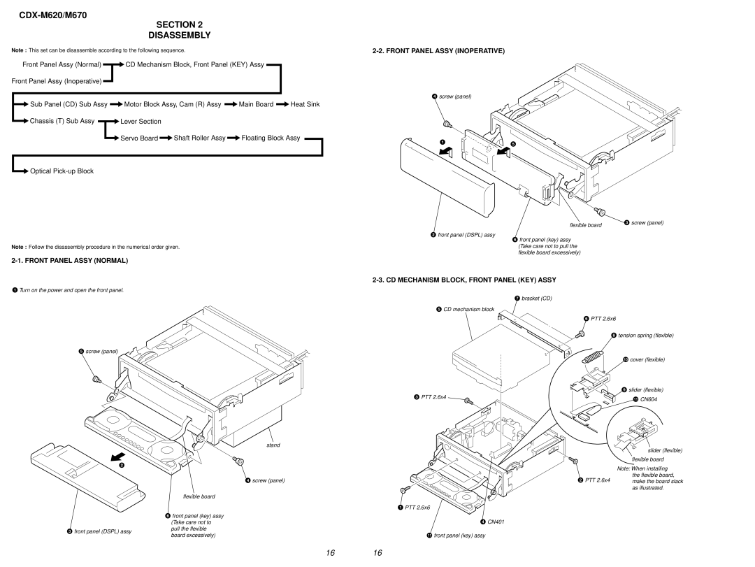
DISASSEMBLY
Note : This set can be disassemble according to the following sequence.
Front Panel Assy (Normal) | CD Mechanism Block, Front Panel (KEY) Assy |
Front Panel Assy (Inoperative) |
|
2-2. FRONT PANEL ASSY (INOPERATIVE)
![]() Sub Panel (CD) Sub Assy
Sub Panel (CD) Sub Assy ![]() Motor Block Assy, Cam (R) Assy
Motor Block Assy, Cam (R) Assy ![]() Main Board
Main Board ![]() Heat Sink
Heat Sink
Chassis (T) Sub Assy | Lever Section |
|
|
| Servo Board | Shaft Roller Assy | Floating Block Assy |
Optical |
|
|
|
Note : Follow the disassembly procedure in the numerical order given.
4 screw (panel)
1
2front panel (DSPL) assy
5
flexible board | 3 screw (panel) |
|
6front panel (key) assy (Take care not to pull the flexible board excessively)
2-1. FRONT PANEL ASSY (NORMAL)
1Turn on the power and open the front panel.
5 screw (panel)
2
3front panel (DSPL) assy
stand
4 screw (panel)
flexible board
6front panel (key) assy (Take care not to pull the flexible board excessively)
2-3. CD MECHANISM BLOCK, FRONT PANEL (KEY) ASSY
7 bracket (CD)
5CD mechanism block
3PTT 2.6x4
1 PTT 2.6x6
4 CN401
qa front panel (key) assy
6PTT 2.6x6
8 tension spring (flexible)
0cover (flexible)
9 slider (flexible)
qa CN604
slider (flexible)
flexible board
Note: When installing
the flexible board,
2 PTT 2.6x4 make the board slack as illustrated.
16 16