THIS NOTE IS COMMON FOR PRINTED WIRING BOARDS AND SCHEMATIC DIAGRAMS.
(In addition to this, the necessary note is printed in each block.)
for schematic diagram:
•All capacitors are in µF unless otherwise noted. pF: µµF 50 WV or less are not indicated except for electrolytics and tantalums.
•All resistors are in Ω and 1/4 W or less unless otherwise specified.
•% : indicates tolerance.
•f : internal component.
•C : panel designation.
Note: The components identified by mark 0or dotted line with mark 0are critical for safety.
Replace only with part number specified.
•A : B+ Line.
•Power voltage is dc 14.4V and fed with regulated dc power supply from ACC and BATT cords.
•Voltages are taken with a VOM (Input impedance 10 MΩ ). Voltage variations may be noted due to normal produc- tion tolerances.
•Waveforms are taken with a oscilloscope.
Voltage variations may be noted due to normal produc- tion tolerances.
•Circled numbers refer to waveforms.
•Signal path.
F : FM
f : AM/MW
J : CD
for printed wiring boards:
•X: parts extracted from the component side.
•Y: parts extracted from the conductor side.
•a : Through hole.
•![]() : Pattern from the side which enables seeing. (The other layer’s patterns are not indicated.)
: Pattern from the side which enables seeing. (The other layer’s patterns are not indicated.)
Caution:
Pattern face side: Parts on the pattern face side seen from the
(Side B) pattern face are indicated.
Parts face side: Parts on the parts face side seen from the
(Side A) | parts face are indicated. |
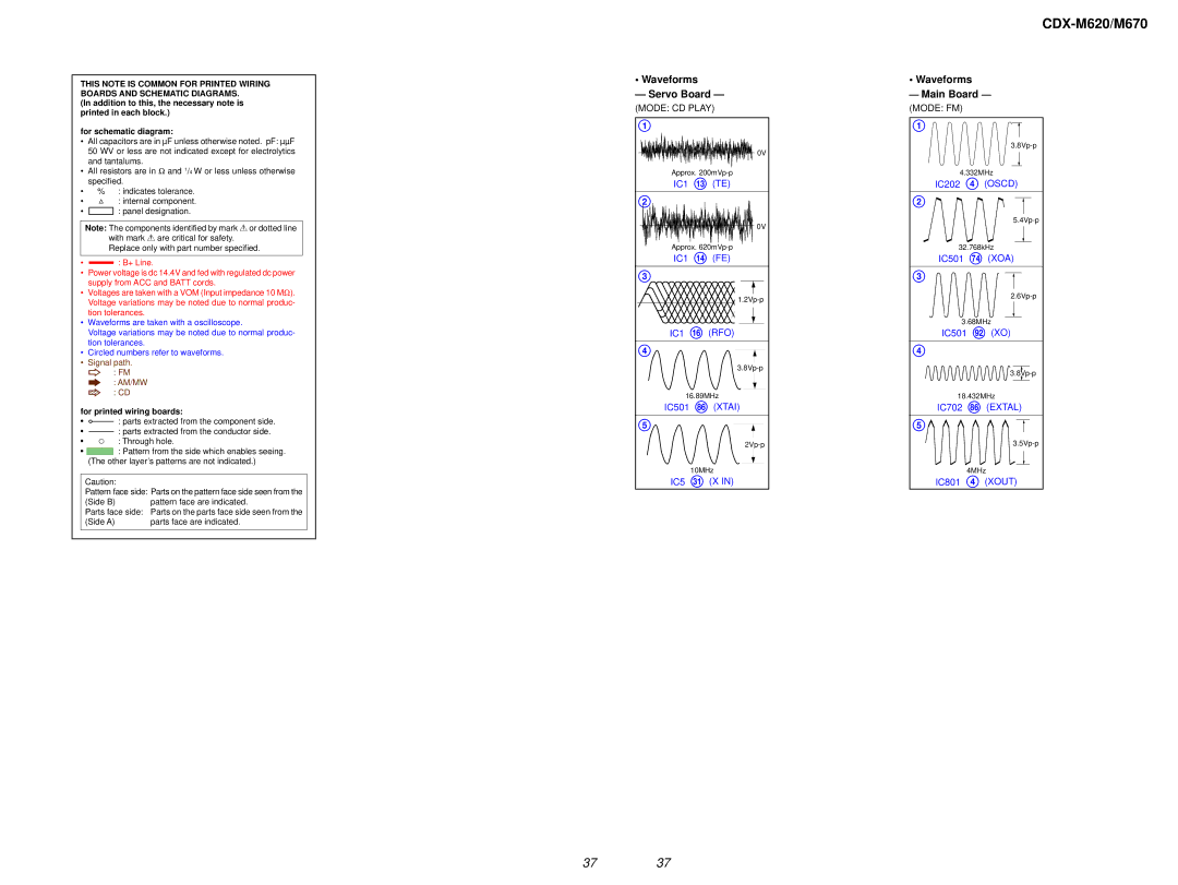
• Waveforms
— Servo Board —
(MODE: CD PLAY)
1 |
|
| 0V |
Approx. | |
IC1 | qd (TE) |
2 |
|
| 0V |
Approx. | |
IC1 | qf (FE) |
3 |
|
| |
IC1 qh (RFO) | |
4 |
|
| |
16.89MHz | |
IC501 ih (XTAI) | |
5 |
|
| |
| 10MHz |
IC5 | ea (X IN) |
CDX-M620/M670
•Waveforms
— Main Board —
(MODE: FM)
1 |
4.332MHz |
IC202 4 (OSCD) |
2 |
32.768kHz |
IC501 uf (XOA) |
3 |
3.68MHz |
IC501 os (XO) |
4 |
18.432MHz |
IC702 ih (EXTAL) |
5 |
4MHz |
IC801 4 (XOUT) |
37 37