CDX-M620/M670
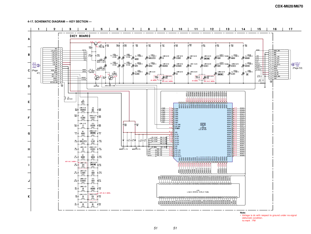
4-17. SCHEMATIC DIAGRAM — KEY SECTION —
(Page 53)
(Page
47)
Note:
• Voltage is dc with respect to ground under
no mark : FM
51 51
(Page 53)
(Page
47)
Note:
• Voltage is dc with respect to ground under
no mark : FM
51 51