Contents
Specifications
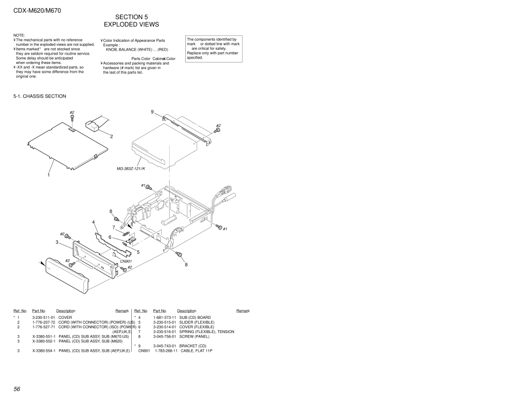
CDX-M620/M670
AEP/UK model
Service Notes
US model
Table of Contents
Disassembly
Phase Alignment
Diagrams
Section General
US Model AEP, UK, E Model
US, AEP, UK, E Model
US Model
AEP, UK, E Model
CDX-M620/M670
CDX-M620/M670
US, AEP, UK, E Model
CDX-M620/M670
Connection
CDX-M620/M670
AEP, UK, E Model Connection
CDX-M620/M670
Section Disassembly
Front Panel Assy Inoperative
Front Panel Assy Normal
CD Mechanism BLOCK, Front Panel KEY Assy
SUB Panel CD SUB Assy
Motor Block ASSY, CAM R Assy
Main Board
Heat Sink
Chassis T SUB Assy
Lever Section
Servo Board
Shaft Roller Assy
Floating Block Assy
Optical PICK-UP Block
CAM L
Section Phase Alignment
ARM A-L ASSY, ARM B-L Assy
Motor Block
Alignment Between ARM A-L Assy and ARM B-L Assy
ARM A-R ASSY, ARM B-R Assy
CAM R
Section Diagrams
IC PIN Descriptions
Rfdc
IC5 CXP84640-072Q CD System Control Servo Board
Self SW
SYS RST
Open KEY
4V SEL
IC702 HD643255A36F SUB System Control Main Board
Circuit Boards Location
Block Diagram CD Section
Ch same as L-ch
Block Diagram Tuner Section
Display Section
Block Diagram Display Section
Waveforms Servo Board
Waveforms Main Board
Printed Wiring Boards CD Mechanism Section
IC1 IC5 IC7
IC B/D
IC B/D
Printed Wiring Boards Main Section
CDX-M620/M670
IC B/D
IC B/D
CDX-M620/M670
CDX-M620/M670
Printed Wiring Board SUB CD Section
CDX-M620/M670
Printed Wiring Board KEY Section
LED5 LED14 LED6 LED15 LED7 LED16
Schematic Diagram KEY Section
Printed Wiring Board Display Section
IC B/D
IC Block Diagrams
IC102 RN5VD53AA-TL
IC305 TDA7406TR
IC62, 901 RRX9000-0601
Section Exploded Views
Chassis Section
Cover
SUB CD Board
CAM Section
64 #2
Main Board Section
113
108 114 107 112 110 115 109 111 104
106 105 107
Front Panel KEY Assy Section
171 172 173 170 174 169
168 166
164 165 167 163 162 159 161 160
Front Panel Dspl Assy Section
CD Mechanism MG-383Z-121//K 254
253 257 259 251 266 265 264 256 255 263
261 260 267 258
262
309 A-3307-422-A Chassis M Complete Assy
CD Mechanism MG-383Z-121//K 304 301 306 307 308 310 314
312 313 305303 311 309 302
CD Mechanism MG-383Z-121//K 351
357 352 359 356
358 353
360 354 355 361
Display
Electrical Parts List
Section
Display Disc in SW KEY
KEY Limit SW
Main
Main BOARD, Complete AEP,UK,E
Buzzer
Elect
Ref. No Description Remark C306 162-965-11
PIN, Connector 16P
PLUG, Connector BUS Control
PIN, Connector 6P
CONNECTOR, Flexible 11P
COIL, Choke
Inductor
Transistor KRC103S
Transistor KRA103S
EXCEPTM670US
Short
Description Remark R389 216-829-11
Main Servo
THERMISTOR, Positive
THERMISTOR, Positive Tuner
Servo BOARD, Complete Capacitor
Servo
CN3
Jumper Resistor
Transistor 2SB1197K-T-146-R Resistor
Servo SUB CD
401 402 404 403 407 408 409 405 406 410 411 412 413414
Revision History