Phase Reverse, High Pass Filter | Control Elements |
|
|
Phase Reverse | |
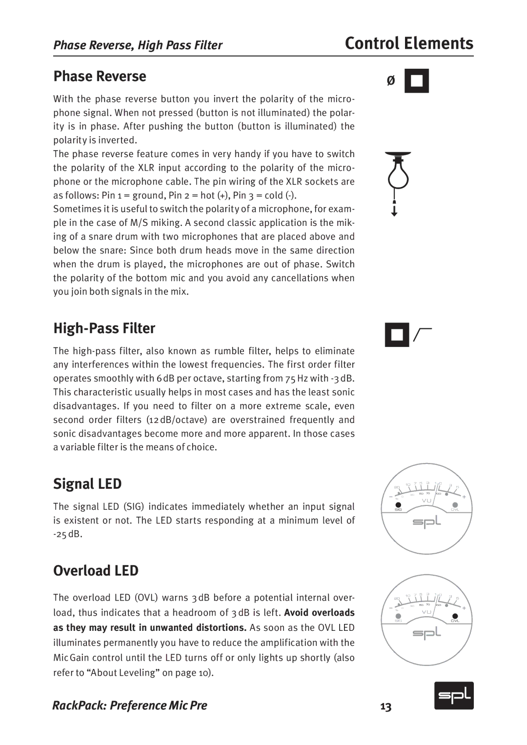
With the phase reverse button you invert the polarity of the micro- phone signal. When not pressed (button is not illuminated) the polar- ity is in phase. After pushing the button (button is illuminated) the polarity is inverted.
The phase reverse feature comes in very handy if you have to switch the polarity of the XLR input according to the polarity of the micro- phone or the microphone cable. The pin wiring of the XLR sockets are as follows: Pin 1 = ground, Pin 2 = hot (+), Pin 3 = cold
Sometimes it is useful to switch the polarity of a microphone, for exam- ple in the case of M/S miking. A second classic application is the mik- ing of a snare drum with two microphones that are placed above and below the snare: Since both drum heads move in the same direction when the drum is played, the microphones are out of phase. Switch the polarity of the bottom mic and you avoid any cancellations when you join both signals in the mix.
High-Pass Filter
The
Signal LED
The signal LED (SIG) indicates immediately whether an input signal is existent or not. The LED starts responding at a minimum level of
20 | 10 | 7 | 5 | 3 | 1 0 | 3 | 5 |
|
|
|
|
|
| ||
% 0 |
| 30 | 50 | 70 | 100 |
|
|
|
| VU |
|
|
| ||
|
|
|
|
|
| ||
SIGOVL
Overload LED
The overload LED (OVL) warns 3 dB before a potential internal over- load, thus indicates that a headroom of 3 dB is left. Avoid overloads as they may result in unwanted distortions. As soon as the OVL LED illuminates permanently you have to reduce the amplification with the Mic Gain control until the LED turns off or only lights up shortly (also refer to “About Leveling” on page 10).
20 | 10 | 7 | 5 | 3 | 1 0 | 3 | 5 |
|
|
|
|
|
| ||
% 0 |
| 30 | 50 | 70 | 100 |
|
|
|
| VU |
|
|
| ||
|
|
|
|
|
| ||
SIGOVL
RackPack: Preference Mic Pre | 13 |
