Five Monitor Series specifications
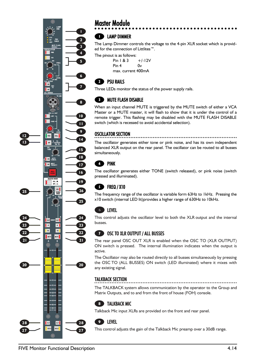
The SoundCraft Five Monitor Series represents a significant advancement in professional audio mixing technology, tailored specifically for live sound environments. Renowned for their high-quality performance and user-friendly interface, these mixing consoles are designed for sound engineers and musicians who demand reliability and flexibility.One of the standout features of the SoundCraft Five is its ergonomic design, which prioritizes ease of use. The console layout is intuitive, allowing for quick adjustments during live performances. With strategically placed faders, knobs, and buttons, engineers can make real-time changes without losing focus on the performance, an essential characteristic for any live set.
Equipped with advanced digital signal processing (DSP), the SoundCraft Five provides unparalleled sound clarity and precision. The built-in EQ features, including parametric equalizers, allow sound engineers to tailor the audio output to the specific acoustics of the venue. This adaptability ensures that performers are always heard at their best, regardless of the environment.
Another key technology in the Five Monitor Series is the compatibility with various audio formats and protocols. Utilizing both analog and digital inputs, these consoles can seamlessly integrate into complex audio setups. This flexibility is crucial for modern performances where multiple audio sources need to be managed efficiently.
The SoundCraft Five also incorporates high-quality preamps that deliver exceptional sound quality. These preamps ensure that every detail of the audio is captured without distortion, providing a warm and professional sound that enhances the overall listening experience.
Durability is a hallmark of the SoundCraft design philosophy. The Five Monitor Series is built to withstand the rigors of touring and live events, featuring rugged construction and reliable components. This resilience ensures that the mixer will perform consistently through various demanding situations.
Furthermore, the intuitive layout includes comprehensive metering options, allowing sound engineers to monitor levels effectively. This visual feedback is vital for maintaining optimal sound quality throughout the performance, helping to avoid potential issues before they arise.
In summary, the SoundCraft Five Monitor Series stands out in the competitive landscape of live sound mixing consoles. With its combination of user-friendly design, advanced DSP technology, high-quality preamps, and robust construction, it meets the diverse needs of modern audio professionals, making it an essential tool for any live performance setup.

