2. 22 PIN BASE HARNESS CONTINUED
Ground When Armed Output (ORANGE)
This wire will show ground when the system is armed.
This wire is used for controlling window modules or additional sensors.
Headlight Output (LT. GREEN/ORANGE)
Locate the vehicle’s headlight wire.
Verification: This wire will register either positive voltage or ground when the headlights are turned on.
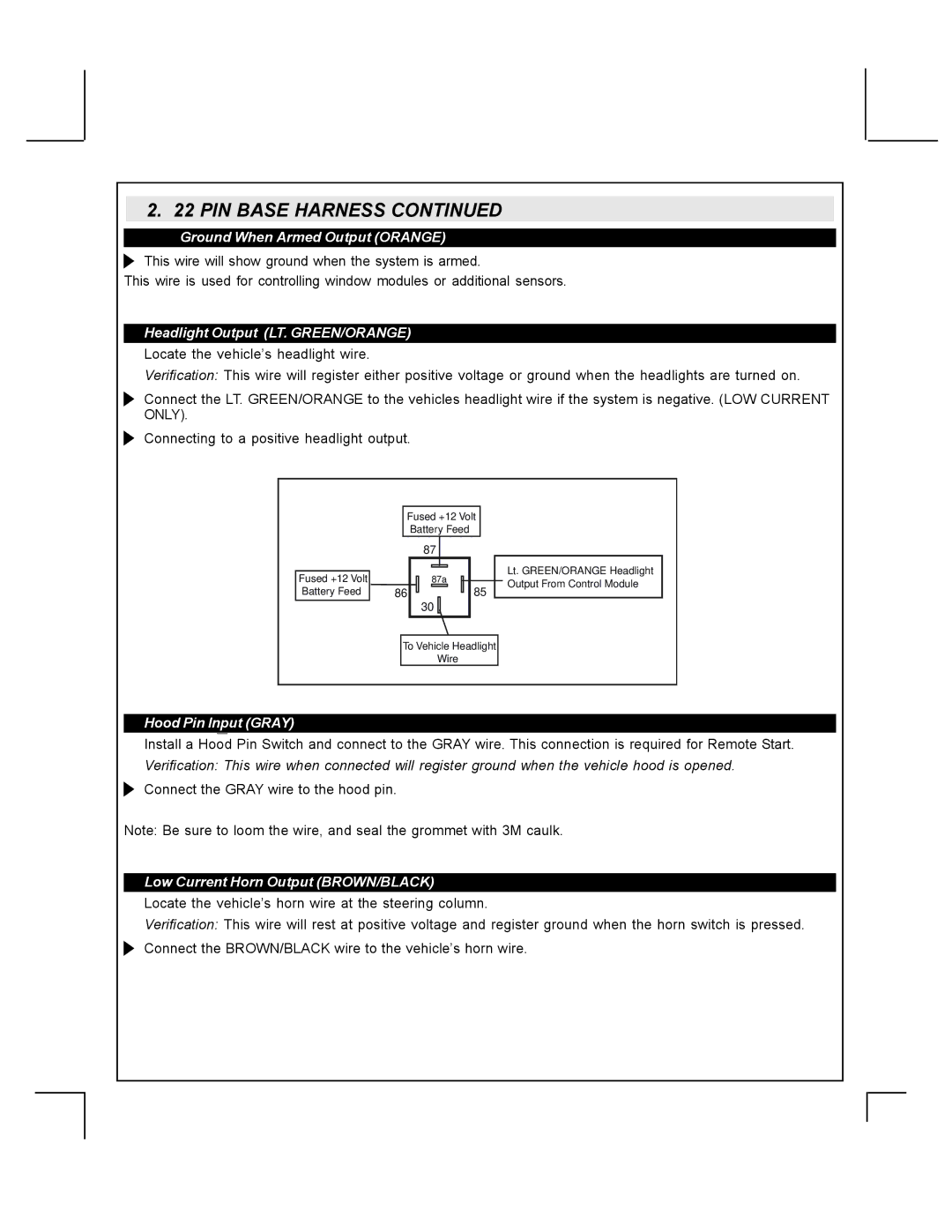
Connect the LT. GREEN/ORANGE to the vehicles headlight wire if the system is negative. (LOW CURRENT ONLY).
Connecting to a positive headlight output.
| Fused +12 Volt |
| ||
|
| Battery Feed |
| |
|
| 87 |
| |
Fused +12 Volt |
| 87a | Lt. GREEN/ORANGE Headlight | |
| Output From Control Module | |||
Battery Feed | 86 | 85 | ||
| ||||
|
| 30 |
| |
| To Vehicle Headlight |
| ||
|
| Wire |
| |
Hood Pin Input (GRAY)
Install a Hood Pin Switch and connect to the GRAY wire. This connection is required for Remote Start. Verification: This wire when connected will register ground when the vehicle hood is opened.
Connect the GRAY wire to the hood pin.
Note: Be sure to loom the wire, and seal the grommet with 3M caulk.
Low Current Horn Output (BROWN/BLACK)
Locate the vehicle’s horn wire at the steering column.
Verification: This wire will rest at positive voltage and register ground when the horn switch is pressed. Connect the BROWN/BLACK wire to the vehicle’s horn wire.
