Motherboard Description |
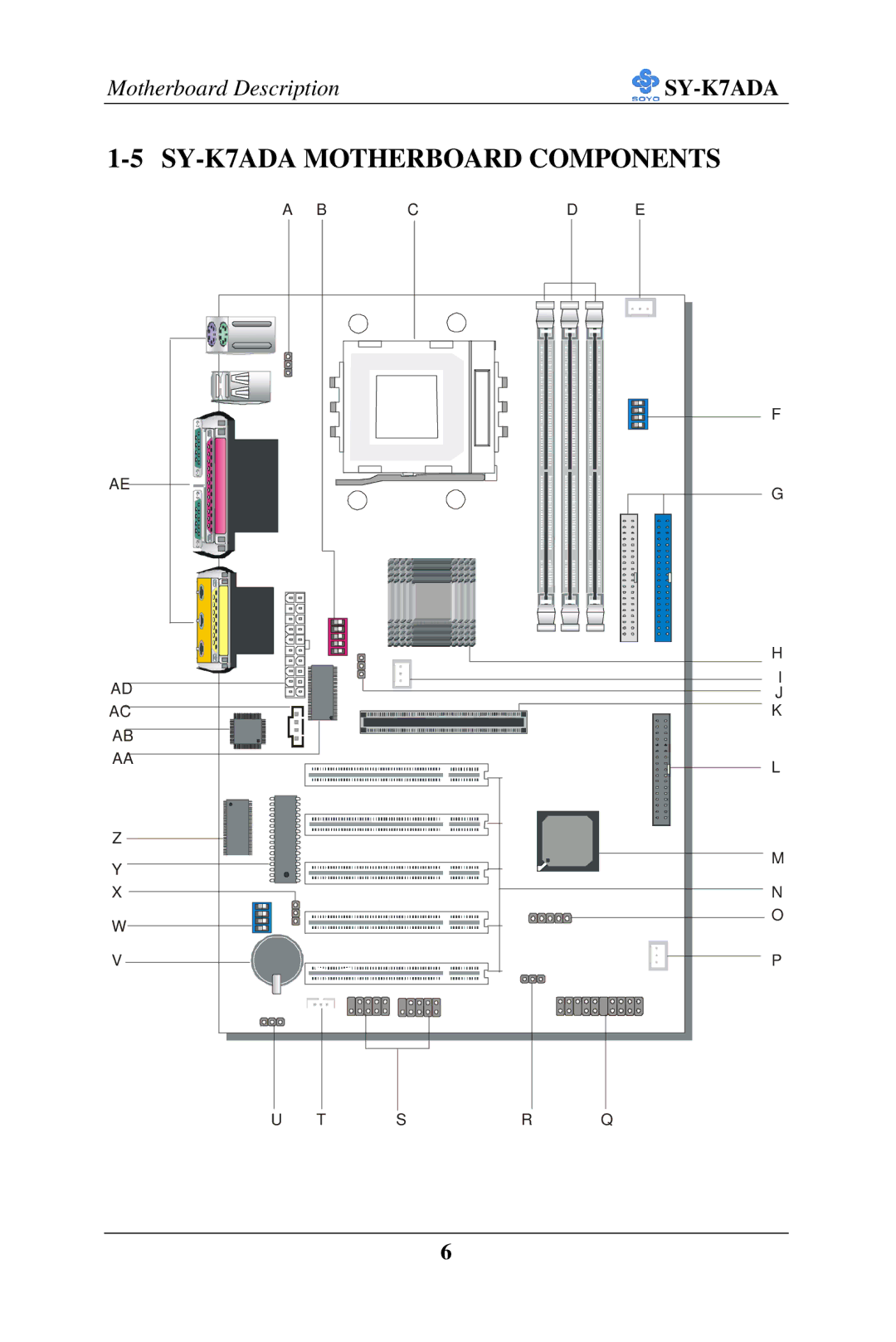
1-5 SY-K7ADA MOTHERBOARD COMPONENTS
AE
AD AC AB AA
Z
Y
X
W
A BCD E
SDRAM |
® |
SDRAM |
F
G
H
I
J
K
L
M
N
O
V
P
U T SR Q
6
Motherboard Description |
AE
AD AC AB AA
Z
Y
X
W
A BCD E
SDRAM |
® |
SDRAM |
F
G
H
I
J
K
L
M
N
O
V
P
U T SR Q
6