Step 3. Connections to the Motherboard
This section tells how to connect internal peripherals and the power supply to the Motherboard.
The internal peripherals consist of IDE devices (HDD,
For more details on connecting internal and external peripherals to your new
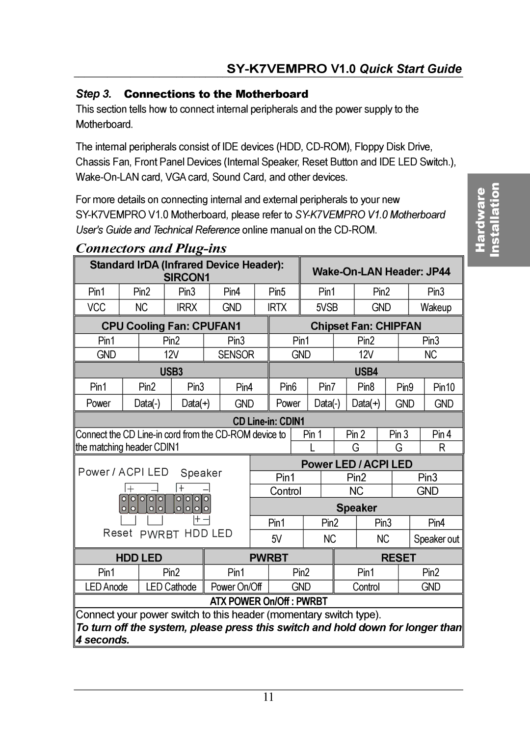
Connectors and Plug-ins
Standard IrDA (Infrared Device Header): |
|
|
|
|
|
| ||||||||||||||||||||||||||||||||||||
|
|
|
|
|
|
|
|
| SIRCON1 |
|
|
|
|
|
|
|
|
|
| |||||||||||||||||||||||
|
|
|
|
|
|
|
|
|
|
|
|
|
|
|
|
|
|
|
|
|
|
|
|
|
|
|
|
|
|
|
|
|
|
| ||||||||
Pin1 |
|
|
| Pin2 |
|
|
| Pin3 |
|
| Pin4 |
| Pin5 |
|
|
|
| Pin1 |
|
| Pin2 |
|
|
|
|
| Pin3 |
| ||||||||||||||
VCC |
|
|
|
| NC |
|
|
| IRRX |
|
| GND |
| IRTX |
|
|
|
| 5VSB |
|
| GND |
|
|
|
| Wakeup |
| ||||||||||||||
|
|
|
|
|
|
|
|
|
|
|
|
|
|
|
|
|
|
|
|
|
|
|
|
|
|
|
|
|
|
|
|
|
|
|
| |||||||
CPU Cooling Fan: CPUFAN1 |
|
|
|
|
| Chipset Fan: CHIPFAN |
| |||||||||||||||||||||||||||||||||||
Pin1 |
|
|
|
|
| Pin2 |
|
|
| Pin3 |
| Pin1 |
|
|
|
|
|
| Pin2 |
|
|
|
|
|
| Pin3 |
| |||||||||||||||
GND |
|
|
|
|
| 12V |
|
| SENSOR |
| GND |
|
|
|
| 12V |
|
|
|
|
|
|
| NC |
| |||||||||||||||||
|
|
|
|
|
|
|
|
|
|
|
|
|
|
|
|
|
|
|
|
|
|
|
|
|
|
|
|
|
|
|
|
|
|
|
|
|
|
|
|
|
|
|
|
|
|
|
|
|
|
| USB3 |
|
|
|
|
|
|
|
|
|
|
|
|
|
| USB4 |
|
|
|
|
|
|
|
|
| ||||||||||
Pin1 |
|
|
|
| Pin2 |
|
| Pin3 |
| Pin4 | Pin6 |
| Pin7 |
|
| Pin8 |
|
| Pin9 |
|
| Pin10 |
| |||||||||||||||||||
Power |
|
|
|
| Data(+) |
| GND | Power |
| Data(+) |
|
| GND |
|
| GND |
| |||||||||||||||||||||||||
|
|
|
|
|
|
|
|
|
|
|
|
|
|
|
|
|
|
|
|
|
|
|
|
|
|
|
|
|
|
|
|
|
|
|
|
|
|
|
| |||
|
|
|
|
|
|
|
|
|
|
|
|
|
|
|
|
|
| CD |
|
|
|
|
|
|
|
|
|
|
|
|
|
|
|
|
| |||||||
Connect the CD |
|
| Pin 1 |
| Pin 2 |
|
| Pin 3 |
|
| Pin 4 |
| ||||||||||||||||||||||||||||||
the matching header CDIN1 |
|
|
|
|
|
|
|
|
| L |
| G |
|
|
| G |
|
| R |
| ||||||||||||||||||||||
|
|
|
|
|
|
|
|
|
|
|
|
|
|
|
|
|
|
|
|
|
|
|
|
|
|
|
|
|
|
|
|
|
|
| ||||||||
Power / ACPI LED |
|
| Speaker |
|
|
|
| Power LED / ACPI LED |
|
|
|
| ||||||||||||||||||||||||||||||
|
|
|
| Pin1 |
|
|
|
| Pin2 |
|
|
|
|
| Pin3 |
| ||||||||||||||||||||||||||
|
|
| + | _ |
|
|
|
|
|
|
|
|
|
|
|
|
|
|
|
|
|
|
|
|
|
|
| |||||||||||||||
|
|
|
|
|
|
|
|
|
|
|
|
|
|
|
| Control |
|
|
|
| NC |
|
|
|
|
| GND |
| ||||||||||||||
|
|
|
|
|
|
|
|
|
|
|
|
|
|
|
|
|
|
|
|
|
|
|
|
|
|
|
| |||||||||||||||
|
|
|
|
|
|
|
|
|
|
|
|
|
|
|
|
|
|
|
|
|
|
|
|
|
|
|
|
|
|
|
|
|
|
|
|
|
|
|
| |||
|
|
|
|
|
|
|
|
|
|
|
|
|
|
|
|
|
|
|
|
|
|
|
|
|
|
|
|
| Speaker |
|
|
|
|
|
|
|
|
| ||||
|
|
|
|
|
|
|
|
|
|
|
|
|
|
|
|
|
|
|
|
| Pin1 |
|
|
|
|
| Pin2 |
|
| Pin3 |
|
|
|
|
| Pin4 |
| |||||
|
|
|
|
|
|
|
|
|
|
|
|
|
|
|
|
|
|
|
|
|
|
|
|
|
|
|
|
|
|
|
|
|
| |||||||||
Reset PWRBT HDD LED |
|
|
|
|
|
|
|
|
|
|
|
|
|
|
| |||||||||||||||||||||||||||
| 5V |
|
|
|
|
| NC |
|
|
| NC |
|
| Speaker out |
| |||||||||||||||||||||||||||
|
|
|
|
|
|
|
|
|
|
|
|
|
|
|
|
|
|
|
|
|
|
|
|
|
|
|
|
|
|
|
| |||||||||||
|
|
|
|
|
|
|
|
|
|
|
|
|
|
|
|
|
|
|
|
|
|
|
|
|
|
|
|
|
|
|
|
|
|
|
|
|
| |||||
|
|
|
|
|
|
|
|
|
|
|
|
|
|
|
|
|
|
|
|
|
|
|
|
|
|
|
|
|
|
|
|
|
|
| ||||||||
HDD LED |
|
|
|
|
|
|
| PWRBT |
|
|
|
|
|
|
|
|
|
|
|
| RESET |
|
|
|
| |||||||||||||||||
Pin1 |
|
|
|
|
| Pin2 |
|
|
| Pin1 |
| Pin2 |
|
|
|
|
|
| Pin1 |
|
|
|
|
|
| Pin2 |
| |||||||||||||||
LED Anode |
|
| LED Cathode |
|
| Power On/Off |
| GND |
|
| Control |
|
|
|
|
|
| GND |
| |||||||||||||||||||||||
|
|
|
|
|
|
|
|
|
|
|
|
|
|
|
|
|
|
|
|
|
|
|
|
|
|
|
|
|
|
|
|
| ||||||||||
|
|
|
|
|
|
|
|
|
|
|
|
|
|
|
| ATX POWER | On/Off : PWRBT |
|
|
|
|
|
|
|
|
|
|
|
|
|
|
| ||||||||||
Connect your power switch to this header (momentary switch type).
To turn off the system, please press this switch and hold down for longer than 4 seconds.
Hardware Installation
11