SR530, Lock-In Amplifier specifications
The SRS Labs Lock-In Amplifier, model SR530, is a powerful tool designed for high-precision measurements in the realm of scientific research and industrial applications. This state-of-the-art instrument excels in extracting small signals from noisy environments, making it an invaluable asset for experiments in fields such as physics, engineering, and materials science.One of the main features of the SR530 is its ability to perform synchronous detection, which is key to improving signal-to-noise ratios. By utilizing a reference signal, the device correlates the incoming signal with the reference to effectively filter out noise, allowing for the accurate measurement of weak signals that might otherwise be obscured. This process of phase-sensitive detection is fundamental to the operation of the Lock-In Amplifier.
The SR530 offers a wide frequency range, covering from 0.1 Hz to 100 kHz. This broad frequency response allows it to handle a diverse array of signals, making it suitable for various applications including optical detection, capacitance measurements, and in many cases, voltammetry. The device is also equipped with multiple inputs and outputs, facilitating the integration with other laboratory equipment and enabling complex experimental setups.
Precision is further enhanced with its adjustable time constant, which allows users to optimize the response time based on experimental needs. The user can choose time constants from 10 microseconds to 10 seconds, accommodating fast dynamic measurements as well as those requiring stability over longer durations.
Another remarkable characteristic of the SR530 is its digital processing capabilities. The device features a highly accurate digital voltage measurement system, minimizing drift and ensuring long-term stability. Additionally, the use of microprocessors enhances data handling and allows for features such as programmable settings, facilitating automated measurements.
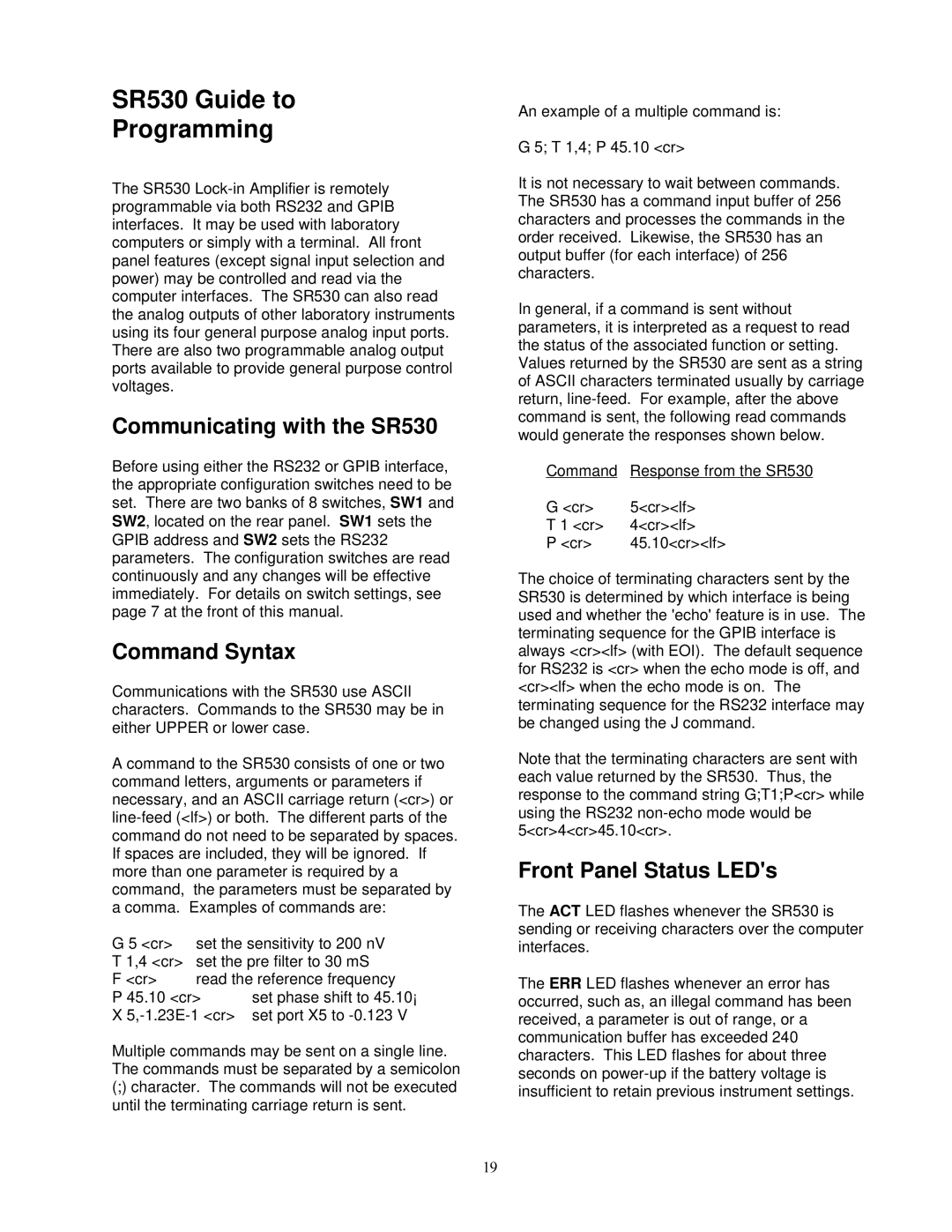
Moreover, the SR530 includes a range of output options, including analog outputs, which can be used for direct signal processing, as well as digital interfaces for integration with computers. This ensures that users can not only capture high-fidelity data but also analyze and display it efficiently.
In conclusion, the SRS Labs SR530 Lock-In Amplifier stands out due to its sophisticated technology, versatile features, and robust performance. Its precision, flexibility, and ease of use make it an ideal choice for researchers and engineers looking to unlock the potential of weak signal measurement in complex environments.
