Dynamic Reserve

Sensitivity Range

LOW

1 V through 500 mV

NORM

100 nV through 50 mV

HIGH

100 nV through 5 mV

Dynamic Reserve

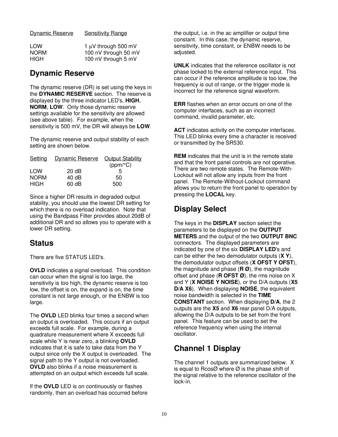
The dynamic reserve (DR) is set using the keys in the DYNAMIC RESERVE section. The reserve is displayed by the three indicator LED's,HIGH, NORM, LOW. Only those dynamic reserve settings available for the sensitivity are allowed (see above table). For example, when the sensitivity is 500 mV, the DR will always be LOW.

The dynamic reserve and output stability of each setting are shown below.

Setting

Dynamic Reserve

Output Stability


(ppm/°C)

LOW

20 dB

5

NORM

40 dB

50

HIGH

60 dB

500

Since a higher DR results in degraded output stability, you should use the lowest DR setting for which there is no overload indication. Note that using the Bandpass Filter provides about 20dB of additional DR and so allows you to operate with a lower DR setting.

Status

There are five STATUS LED's.

OVLD indicates a signal overload. This condition can occur when the signal is too large, the sensitivity is too high, the dynamic reserve is too low, the offset is on, the expand is on, the time constant is not large enough, or the ENBW is too large.

The OVLD LED blinks four times a second when an output is overloaded. This occurs if an output exceeds full scale. For example, during a quadrature measurement where X exceeds full scale while Y is near zero, a blinking OVLD indicates that it is safe to take data from the Y output since only the X output is overloaded. The signal path to the Y output is not overloaded. OVLD also blinks if a noise measurement is attempted on an output which exceeds full scale.

If the OVLD LED is on continuously or flashes randomly, then an overload has occurred before

the output, i.e. in the ac amplifier or output time constant. In this case, the dynamic reserve, sensitivity, time constant, or ENBW needs to be adjusted.

UNLK indicates that the reference oscillator is not phase locked to the external reference input. This can occur if the reference amplitude is too low, the frequency is out of range, or the trigger mode is incorrect for the reference signal waveform.

ERR flashes when an error occurs on one of the computer interfaces, such as an incorrect command, invalid parameter, etc.

ACT indicates activity on the computer interfaces. This LED blinks every time a character is received or transmitted by the SR530.

REM indicates that the unit is in the remote state and that the front panel controls are not operative. There are two remote states. The Remote-With- Lockout will not allow any inputs from the front panel. The Remote-Without-Lockout command allows you to return the front panel to operation by pressing the LOCAL key.

Display Select

The keys in the DISPLAY section select the parameters to be displayed on the OUTPUT METERS and the output of the two OUTPUT BNC connectors. The displayed parameters are indicated by one of the six DISPLAY LED's and can be either the two demodulator outputs (X Y), the demodulator output offsets (X OFST Y OFST), the magnitude and phase (R Ø), the magnitude offset and phase (R OFST Ø), the rms noise on X and Y (X NOISE Y NOISE), or the D/A outputs (X5 D/A X6). When displaying NOISE, the equivalent noise bandwidth is selected in the TIME CONSTANT section. When displaying D/A, the 2 outputs are the X5 and X6 rear panel D/A outputs, allowing the D/A outputs to be set from the front panel. This feature can be used to set the reference frequency when using the internal oscillator.

Channel 1 Display

The channel 1 outputs are summarized below. X is equal to RcosØ where Ø is the phase shift of the signal relative to the reference oscillator of the lock-in.

10

Page 14
Image 14
SRS Labs Lock-In Amplifier, SR530 manual Dynamic Reserve, Status, Display Select, Channel 1 Display

SR530, Lock-In Amplifier specifications

The SRS Labs Lock-In Amplifier, model SR530, is a powerful tool designed for high-precision measurements in the realm of scientific research and industrial applications. This state-of-the-art instrument excels in extracting small signals from noisy environments, making it an invaluable asset for experiments in fields such as physics, engineering, and materials science.

One of the main features of the SR530 is its ability to perform synchronous detection, which is key to improving signal-to-noise ratios. By utilizing a reference signal, the device correlates the incoming signal with the reference to effectively filter out noise, allowing for the accurate measurement of weak signals that might otherwise be obscured. This process of phase-sensitive detection is fundamental to the operation of the Lock-In Amplifier.

The SR530 offers a wide frequency range, covering from 0.1 Hz to 100 kHz. This broad frequency response allows it to handle a diverse array of signals, making it suitable for various applications including optical detection, capacitance measurements, and in many cases, voltammetry. The device is also equipped with multiple inputs and outputs, facilitating the integration with other laboratory equipment and enabling complex experimental setups.

Precision is further enhanced with its adjustable time constant, which allows users to optimize the response time based on experimental needs. The user can choose time constants from 10 microseconds to 10 seconds, accommodating fast dynamic measurements as well as those requiring stability over longer durations.

Another remarkable characteristic of the SR530 is its digital processing capabilities. The device features a highly accurate digital voltage measurement system, minimizing drift and ensuring long-term stability. Additionally, the use of microprocessors enhances data handling and allows for features such as programmable settings, facilitating automated measurements.

Moreover, the SR530 includes a range of output options, including analog outputs, which can be used for direct signal processing, as well as digital interfaces for integration with computers. This ensures that users can not only capture high-fidelity data but also analyze and display it efficiently.

In conclusion, the SRS Labs SR530 Lock-In Amplifier stands out due to its sophisticated technology, versatile features, and robust performance. Its precision, flexibility, and ease of use make it an ideal choice for researchers and engineers looking to unlock the potential of weak signal measurement in complex environments.