ASSEMBLY INSTRUCTIONS
STEP 4
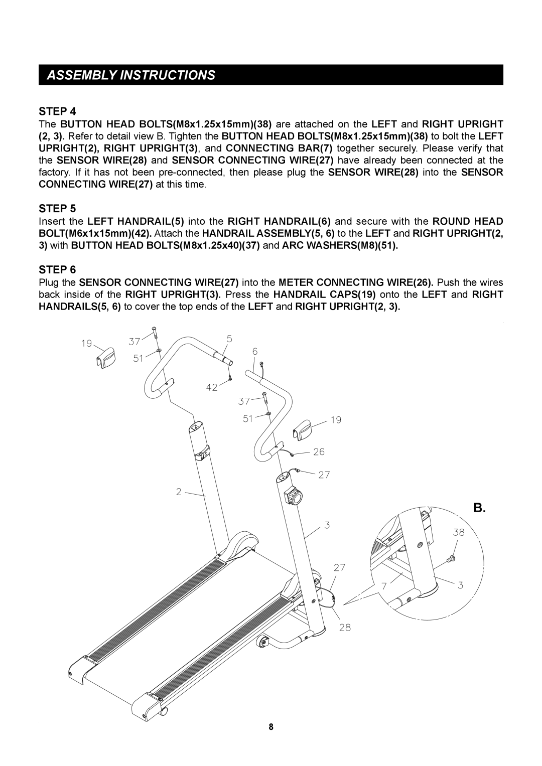
The BUTTON HEAD BOLTS(M8x1.25x15mm)(38) are attached on the LEFT and RIGHT UPRIGHT (2, 3). Refer to detail view B. Tighten the BUTTON HEAD BOLTS(M8x1.25x15mm)(38) to bolt the LEFT UPRIGHT(2), RIGHT UPRIGHT(3), and CONNECTING BAR(7) together securely. Please verify that the SENSOR WIRE(28) and SENSOR CONNECTING WIRE(27) have already been connected at the factory. If it has not been
STEP 5
Insert the LEFT HANDRAIL(5) into the RIGHT HANDRAIL(6) and secure with the ROUND HEAD BOLT(M6x1x15mm)(42). Attach the HANDRAIL ASSEMBLY(5, 6) to the LEFT and RIGHT UPRIGHT(2, 3) with BUTTON HEAD BOLTS(M8x1.25x40)(37) and ARC WASHERS(M8)(51).
STEP 6
Plug the SENSOR CONNECTING WIRE(27) into the METER CONNECTING WIRE(26). Push the wires back inside of the RIGHT UPRIGHT(3). Press the HANDRAIL CAPS(19) onto the LEFT and RIGHT HANDRAILS(5, 6) to cover the top ends of the LEFT and RIGHT UPRIGHT(2, 3).
B.
8
