FLOW CONTROL KIT INSTRUCTIONS
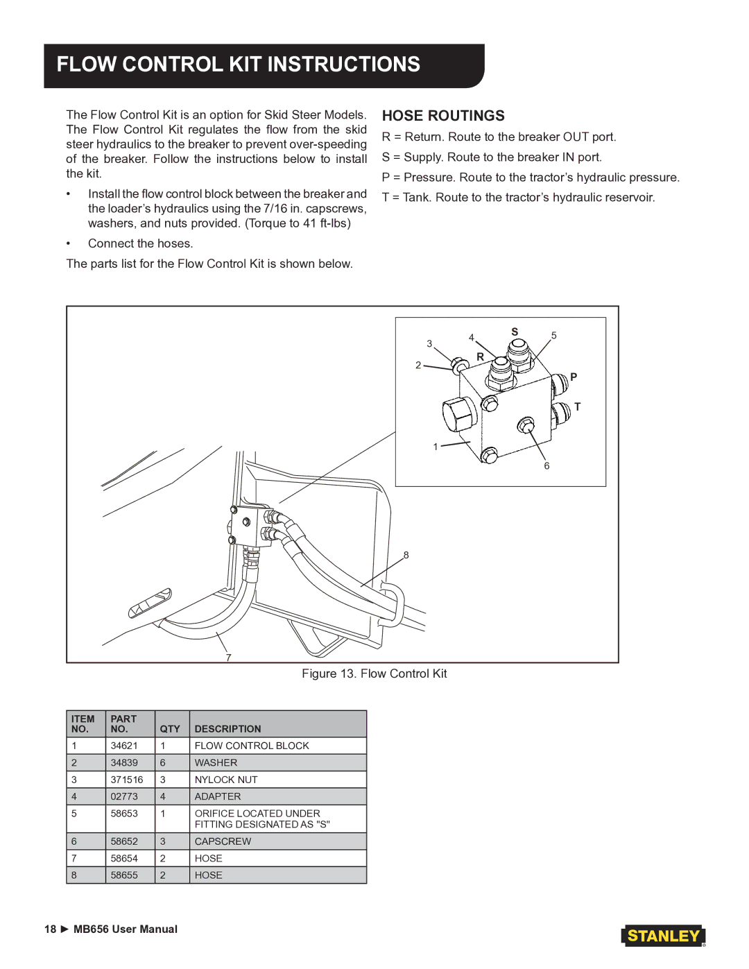
The Flow Control Kit is an option for Skid Steer Models. The Flow Control Kit regulates the flow from the skid steer hydraulics to the breaker to prevent
•Install the flow control block between the breaker and the loader’s hydraulics using the 7/16 in. capscrews, washers, and nuts provided. (Torque to 41
•Connect the hoses.
The parts list for the Flow Control Kit is shown below.
HOSE ROUTINGS
R = Return. Route to the breaker OUT port. S = Supply. Route to the breaker IN port.
P = Pressure. Route to the tractor’s hydraulic pressure. T = Tank. Route to the tractor’s hydraulic reservoir.
3 | 4 | S | 5 |
| |||
| R |
| |
2 |
|
| |
|
| P | |
|
|
| |
|
|
| T |
| 1 |
|
|
|
|
| 6 |
8 |
|
|
|
7 |
|
|
|
Figure 13. Flow Control Kit
ITEM | PART | QTY | DESCRIPTION |
NO. | NO. | ||
1 | 34621 | 1 | FLOW CONTROL BLOCK |
2 | 34839 | 6 | WASHER |
|
|
|
|
3 | 371516 | 3 | NYLOCK NUT |
4 | 02773 | 4 | ADAPTER |
|
|
|
|
5 | 58653 | 1 | ORIFICE LOCATED UNDER |
|
|
| FITTING DESIGNATED AS "S" |
6 | 58652 | 3 | CAPSCREW |
7 | 58654 | 2 | HOSE |
|
|
|
|
8 | 58655 | 2 | HOSE |
18 ► MB656 User Manual
