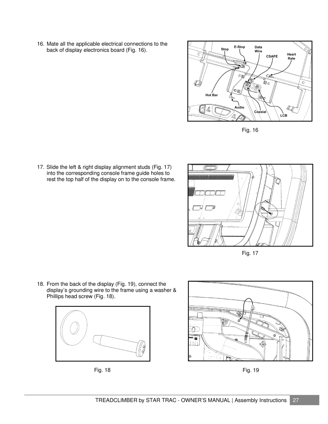
16.Mate all the applicable electrical connections to the back of display electronics board (Fig. 16).
Fig. 16
17.Slide the left & right display alignment studs (Fig. 17) into the corresponding console frame guide holes to rest the top half of the display on to the console frame.
Fig. 17
18.From the back of the display (Fig. 19), connect the display’s grounding wire to the frame using a washer & Phillips head screw (Fig. 18).
Fig. 18 | Fig. 19 |
TREADCLIMBER by STAR TRAC - OWNER’S MANUAL Assembly Instructions 27
