CONTROLS AND SWITCHES

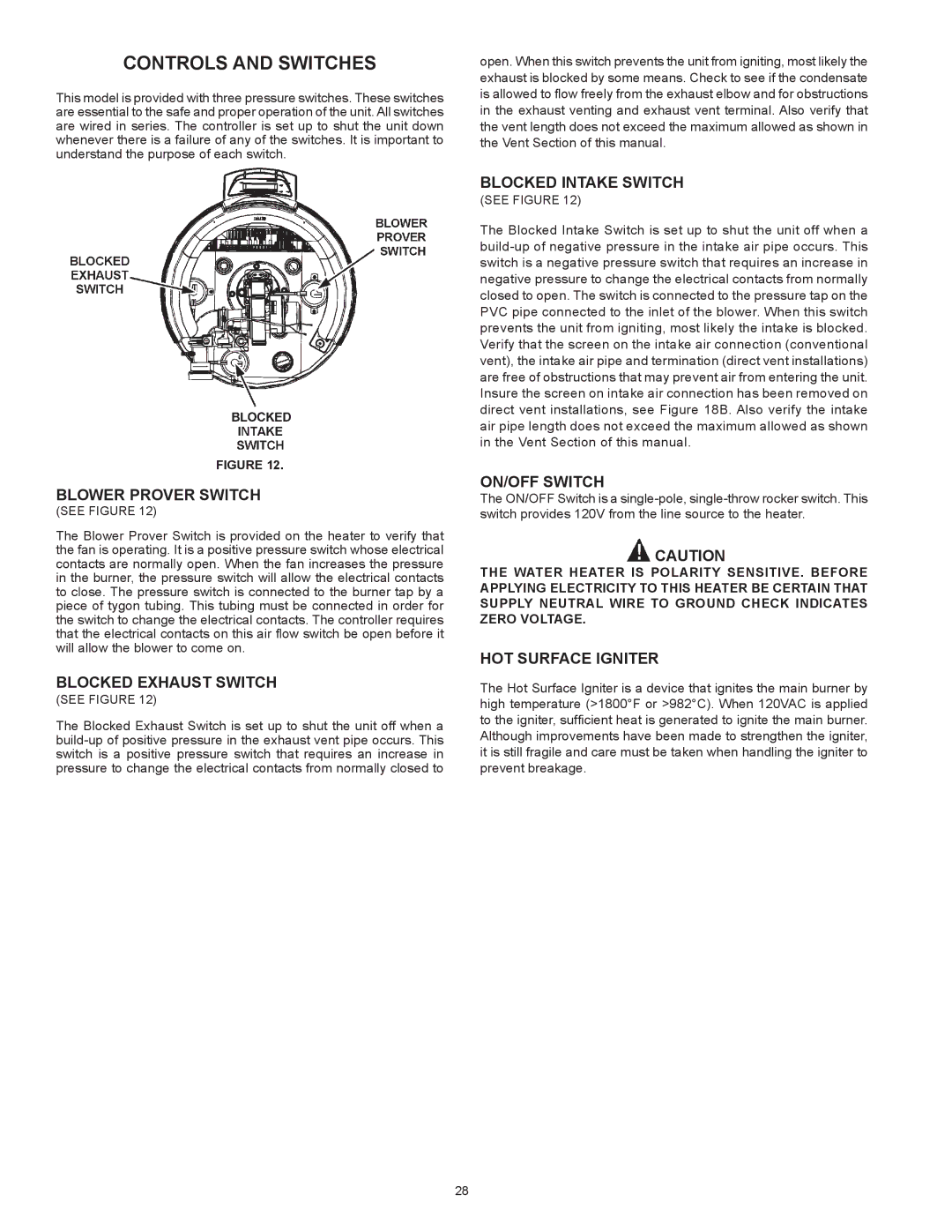
This model is provided with three pressure switches. These switches are essential to the safe and proper operation of the unit. All switches are wired in series. The controller is set up to shut the unit down whenever there is a failure of any of the switches. It is important to understand the purpose of each switch.

FIGURE 12.

BLOWER PROVER SWITCH

(SEE FIGURE 12)

The Blower Prover Switch is provided on the heater to verify that the fan is operating. It is a positive pressure switch whose electrical contacts are normally open. When the fan increases the pressure in the burner, the pressure switch will allow the electrical contacts to close. The pressure switch is connected to the burner tap by a piece of tygon tubing. This tubing must be connected in order for the switch to change the electrical contacts. The controller requires that the electrical contacts on this air flow switch be open before it will allow the blower to come on.

BLOCKED EXHAUST SWITCH

(SEE FIGURE 12)

The Blocked Exhaust Switch is set up to shut the unit off when a build-up of positive pressure in the exhaust vent pipe occurs. This switch is a positive pressure switch that requires an increase in pressure to change the electrical contacts from normally closed to

open. When this switch prevents the unit from igniting, most likely the exhaust is blocked by some means. Check to see if the condensate is allowed to flow freely from the exhaust elbow and for obstructions in the exhaust venting and exhaust vent terminal. Also verify that the vent length does not exceed the maximum allowed as shown in the Vent Section of this manual.

BLOCKED INTAKE SWITCH

(SEE FIGURE 12)

The Blocked Intake Switch is set up to shut the unit off when a build-up of negative pressure in the intake air pipe occurs. This switch is a negative pressure switch that requires an increase in negative pressure to change the electrical contacts from normally closed to open. The switch is connected to the pressure tap on the PVC pipe connected to the inlet of the blower. When this switch prevents the unit from igniting, most likely the intake is blocked. Verify that the screen on the intake air connection (conventional vent), the intake air pipe and termination (direct vent installations) are free of obstructions that may prevent air from entering the unit. Insure the screen on intake air connection has been removed on direct vent installations, see Figure 18B. Also verify the intake air pipe length does not exceed the maximum allowed as shown in the Vent Section of this manual.

ON/OFF SWITCH

The ON/OFF Switch is a single-pole, single-throw rocker switch. This switch provides 120V from the line source to the heater.

CAUTION

THE WATER HEATER IS POLARITY SENSITIVE. BEFORE APPLYING ELECTRICITY TO THIS HEATER BE CERTAIN THAT SUPPLY NEUTRAL WIRE TO GROUND CHECK INDICATES ZERO VOLTAGE.

HOT SURFACE IGNITER

The Hot Surface Igniter is a device that ignites the main burner by high temperature (>1800°F or >982°C). When 120VAC is applied to the igniter, sufficient heat is generated to ignite the main burner. Although improvements have been made to strengthen the igniter, it is still fragile and care must be taken when handling the igniter to prevent breakage.

28

Page 28
Image 28
State Industries Power Vent/Power Direct Vent Gas Models Blower Prover Switch, Blocked Exhaust Switch, ON/OFF Switch

Power Vent/Power Direct Vent Gas Models specifications

State Industries offers a range of power vent and power direct vent gas models that cater to various residential and commercial heating needs. These models are designed for efficiency, safety, and convenience, making them a popular choice among consumers seeking reliable water heating solutions.

One of the standout features of State Industries' power vent models is their ability to vent directly through walls or roofs, enabling installation in locations where traditional venting methods may pose challenges. This flexibility makes them ideal for homes without suitable chimney access. The power vent system employs a fan to push exhaust gases out, ensuring efficient operation even in cases where vertical venting is not feasible.

The power direct vent models take this a step further by utilizing sealed combustion technology. This means they draw air for combustion from outside the home, which significantly reduces the risk of backdrafts and improves indoor air quality. The dual-venting system of these models also enhances their efficiency, as it allows for better control of air flow and exhaust.

State Industries incorporates advanced technologies in their gas models, including electronic ignition systems that eliminate the need for a standing pilot light. This feature not only enhances energy efficiency but also adds convenience for users. Moreover, these models come equipped with LED indicators that provide real-time status updates, enabling users to monitor their units easily.

Durability and reliability are hallmarks of State Industries products. The tanks are constructed with high-quality materials and feature protective coatings that inhibit corrosion, ensuring a long lifespan. In addition to this, many models are backed by extended warranties, providing peace of mind for consumers.

Energy efficiency is a critical characteristic of these gas models, with many units meeting or exceeding energy efficiency standards set by the Environmental Protection Agency (EPA). This results in lower utility bills and a reduced environmental impact. With adjustable temperature settings, users can optimize their water heating experience while conserving energy.

In conclusion, State Industries' power vent and power direct vent gas models stand out for their flexibility in installation, advanced technologies, and energy-efficient operation. Whether for residential or commercial use, these models offer high performance and reliability, ensuring that users enjoy a consistent and efficient hot water supply.