WARNING

NEVER OPERATE THE HEATER UNLESS IT IS VENTED TO THE

OUTDOORSAND HASADEQUATEAIR SUPPLYTOAVOID RISKS OF IMPROPER OPERATION, FIRE, EXPLOSION OR ASPHYXIATION.

VENT PIPE TERMINATION

NOTE: Before installing venting, determine place of vent pipe termination. See Figure 5 and 6 before proceeding.

CAUTION

DO NOT TERMINATE THE VENTING WHERE NOISE FROM THE EXHAUST OR INTAKE WILL BE OBJECTIONABLE. THIS INCLUDES LOCATIONSCLOSETOORACROSSFROMWINDOWSAND DOORS. AVOID ANCHORING THE VENT AND INTAKE PIPES DIRECTLY TO FRAMEDWALLS,FLOORSORCEILINGSUNLESSRUBBERISOLATION PIPEHANGERSAREUSED.THISPREVENTSANYVIBRATIONSFROM BEING TRANSMITTED INTO THE LIVING SPACES.

IMPORTANT

The vent system must terminate so that proper clearances are maintained as cited in local codes or the current editions of the National Fuel Gas Code, ANSI Z223.1/NFPA 54 or the Natural Gas and Propane Installation Code, CAN/CSA-B149.1.

Do not terminate the exhaust vent terminal over public area where condensate or vapor can cause nuisance or hazard.

Plan the vent system layout so that proper clearances are maintained from plumbing and wiring.

Vent pipes serving power vented appliances are classified by building codes as "vent connectors". Required clearances from combustible materials must be provided in accordance with information in this manual under LOCATION OF HEATER and CLEARANCES, and with National Fuel Gas Code and local Codes.

WARNING

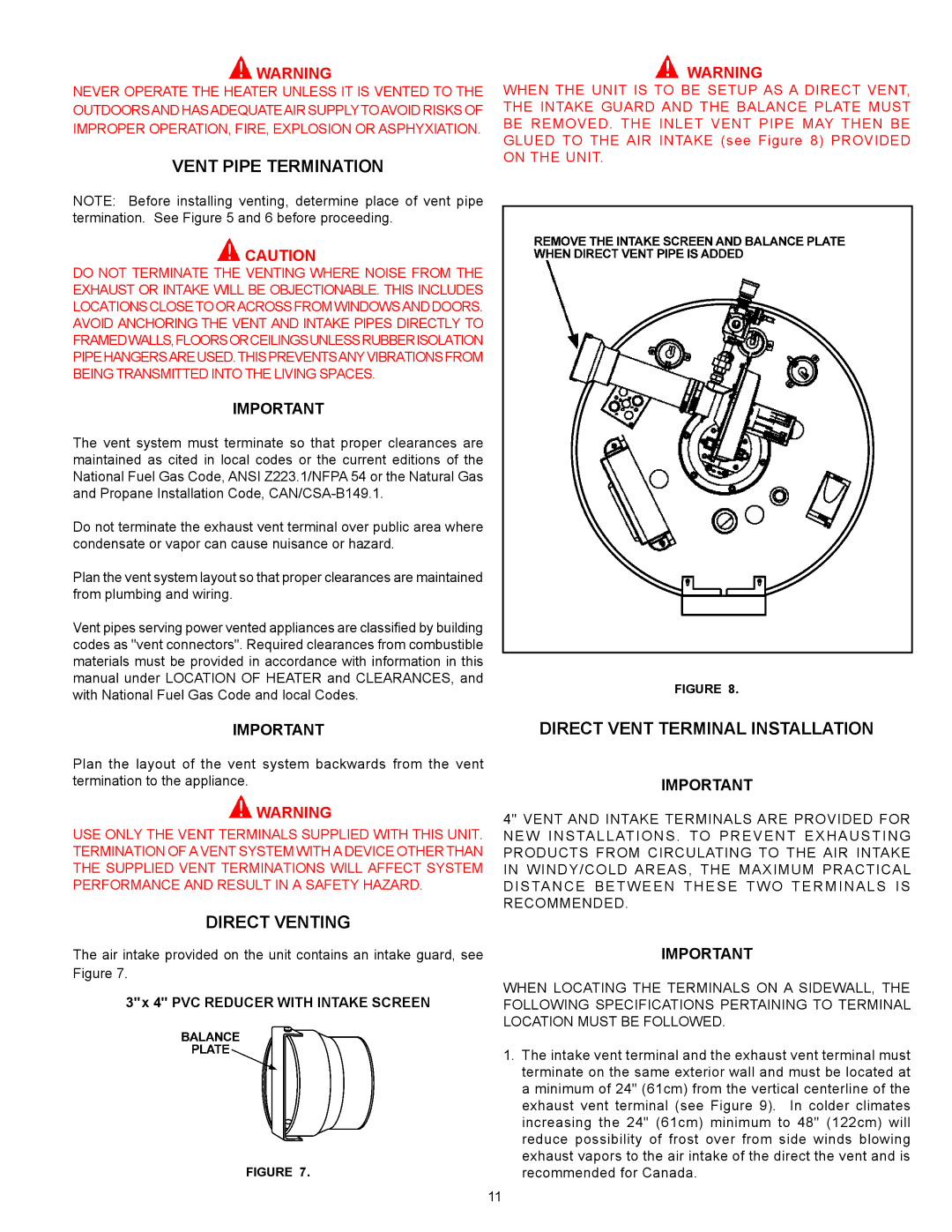
WHEN THE UNIT IS TO BE SETUP AS A DIRECT VENT, THE INTAKE GUARD AND THE BALANCE PLATE MUST BE REMOVED. THE INLET VENT PIPE MAY THEN BE GLUED TO THE AIR INTAKE (see Figure 8) PROVIDED ON THE UNIT.

FIGURE 8.

IMPORTANT

Plan the layout of the vent system backwards from the vent termination to the appliance.

WARNING

USE ONLY THE VENT TERMINALS SUPPLIED WITH THIS UNIT. TERMINATION OF A VENT SYSTEM WITH A DEVICE OTHER THAN THE SUPPLIED VENT TERMINATIONS WILL AFFECT SYSTEM PERFORMANCE AND RESULT IN A SAFETY HAZARD.

DIRECT VENTING

The air intake provided on the unit contains an intake guard, see

Figure 7.

3"x 4" PVC REDUCER WITH INTAKE SCREEN

FIGURE 7.

DIRECT VENT TERMINAL INSTALLATION

IMPORTANT

4" VENT AND INTAKE TERMINALS ARE PROVIDED FOR NEW INSTALLATIONS . TO PREVENT EXHAUSTING PRODUCTS FROM CIRCULATING TO THE AIR INTAKE IN WINDY/COLD AREAS, THE MAXIMUM PRACTICAL DISTANCE BETWEEN THESE TWO TERMINALS IS RECOMMENDED.

IMPORTANT

WHEN LOCATING THE TERMINALS ON A SIDEWALL, THE FOLLOWING SPECIFICATIONS PERTAINING TO TERMINAL LOCATION MUST BE FOLLOWED.

1.The intake vent terminal and the exhaust vent terminal must terminate on the same exterior wall and must be located at a minimum of 24" (61cm) from the vertical centerline of the exhaust vent terminal (see Figure 9). In colder climates increasing the 24" (61cm) minimum to 48" (122cm) will reduce possibility of frost over from side winds blowing exhaust vapors to the air intake of the direct the vent and is recommended for Canada.

11

Page 11
Image 11
State Industries SUF-130-400, SUF-130-300 warranty Vent Pipe Termination, Direct Venting, Direct Vent Terminal Installation

SUF-130-300, SUF-130-400 specifications

State Industries, a renowned leader in the manufacturing of high-efficiency commercial water heaters, has established a strong reputation with its SUF-130-400 and SUF-130-300 models. These units are engineered for optimal performance and energy savings, making them ideal choices for various applications in industries such as hospitality, healthcare, and manufacturing.

The SUF-130-400 model offers an impressive 400,000 BTU per hour input, ensuring rapid heating and consistent hot water supply even during peak demand periods. This model is designed with a durable stainless-steel construction, providing longevity and resistance to corrosion, which is essential for demanding environments. It features a high-efficiency burner that maximizes combustion efficiency and minimizes emissions, making it a sustainable choice for businesses looking to reduce their environmental impact.

On the other hand, the SUF-130-300 model, with a slightly lower input of 300,000 BTU per hour, is perfect for smaller operations that still require a reliable and efficient hot water solution. Despite its lower capacity, this model does not compromise on performance. It incorporates advanced insulation technology that significantly reduces heat loss, enhancing overall operational efficiency and reducing energy costs.

Both models utilize a proven electronic ignition system, ensuring reliable starting and reducing the need for constant pilot light maintenance. This technology is enhanced by a highly responsive digital control system that allows users to easily monitor and adjust temperatures as needed, further promoting intuitive operation and energy savings.

Safety is a priority with these units, as they are equipped with built-in safety mechanisms including flame roll-out switches and pressure relief valves, ensuring safe operation even under the most rigorous conditions. Additionally, the easy-access design facilitates straightforward maintenance and servicing, minimizing downtime and allowing for quick responses to any operational issues.

In conclusion, the State Industries SUF-130-400 and SUF-130-300 models represent the pinnacle of efficiency and reliability in commercial water heating. Their robust construction, advanced technology, and user-friendly features make them an excellent investment for any business requiring consistent hot water supply without compromising on performance or energy efficiency. These models are poised to meet the challenges of modern water heating needs while ensuring sustainability and safety.