5-3 Hopper Loader Conversion Operation
The
If you are familiar with the operation of 9955 and 9965 proportioning hopper loaders, the
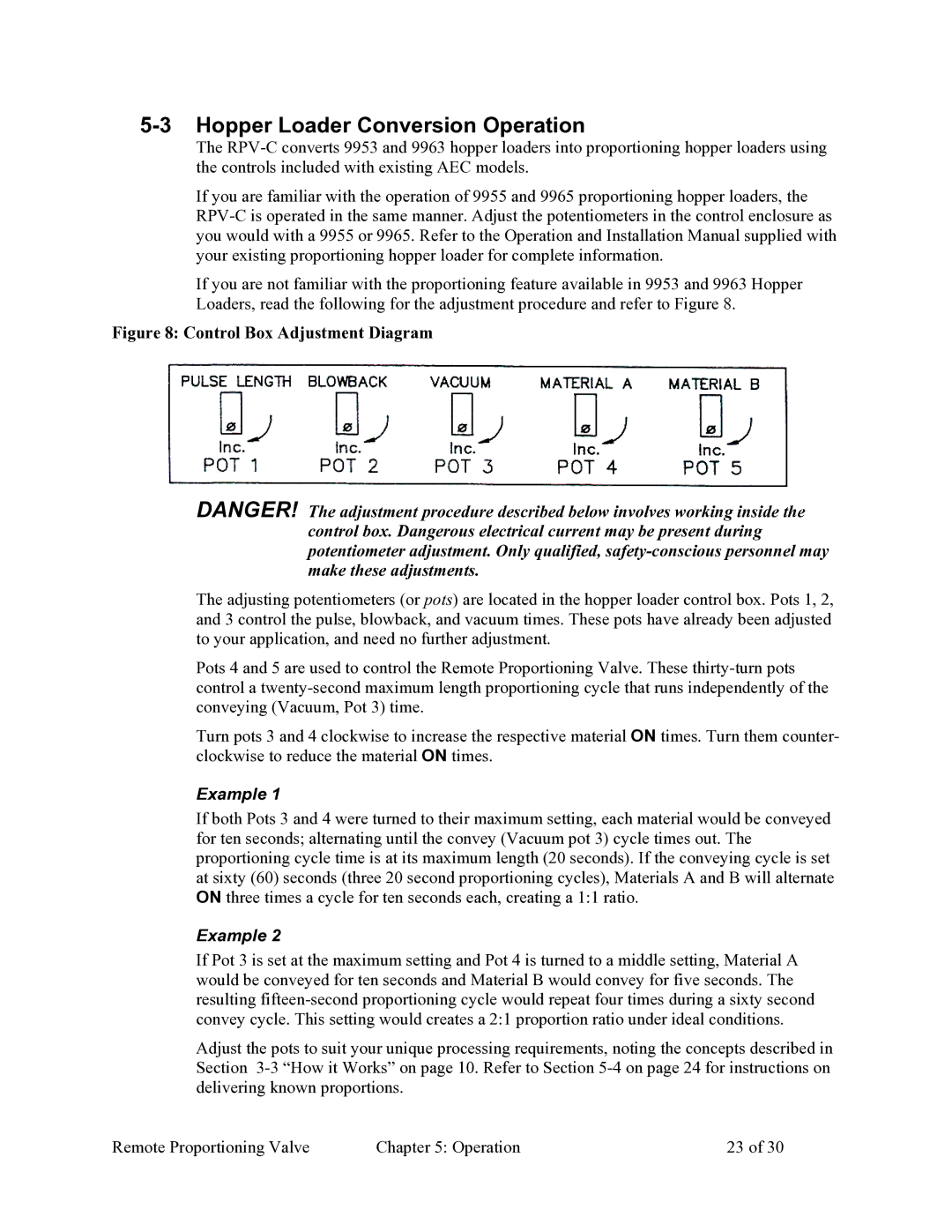
If you are not familiar with the proportioning feature available in 9953 and 9963 Hopper Loaders, read the following for the adjustment procedure and refer to Figure 8.
Figure 8: Control Box Adjustment Diagram
DANGER! The adjustment procedure described below involves working inside the control box. Dangerous electrical current may be present during potentiometer adjustment. Only qualified,
The adjusting potentiometers (or pots) are located in the hopper loader control box. Pots 1, 2, and 3 control the pulse, blowback, and vacuum times. These pots have already been adjusted to your application, and need no further adjustment.
Pots 4 and 5 are used to control the Remote Proportioning Valve. These
Turn pots 3 and 4 clockwise to increase the respective material ON times. Turn them counter- clockwise to reduce the material ON times.
Example 1
If both Pots 3 and 4 were turned to their maximum setting, each material would be conveyed for ten seconds; alternating until the convey (Vacuum pot 3) cycle times out. The proportioning cycle time is at its maximum length (20 seconds). If the conveying cycle is set at sixty (60) seconds (three 20 second proportioning cycles), Materials A and B will alternate ON three times a cycle for ten seconds each, creating a 1:1 ratio.
Example 2
If Pot 3 is set at the maximum setting and Pot 4 is turned to a middle setting, Material A would be conveyed for ten seconds and Material B would convey for five seconds. The resulting
Adjust the pots to suit your unique processing requirements, noting the concepts described in Section
Remote Proportioning Valve | Chapter 5: Operation | 23 of 30 |
