0volts neg
carbon brushes
copper slip rings
on rotor
alternator rotor

alternator
stator
14 volts
B+
main positive output
| 0 volts | B |
|
| A | 14 volts | |||
| neg |
|
| ||||||
|
|
|
|
| |||||
|
|
|
|
|
|
|
| B+ | |
|
|
|
|
|
|
|
| ||
|
|
|
|
|
|
| main positive output | ||
B - |
|
|
|
|
|
|
| ||
alternator case |
|
|
|
|
|
|
| ||
|
|
|
|
|
|
| |||
|
|
|
|
|
|
|
|
|
|
Diagram 2
B - | Diagram 1 |
alternator case | |
|
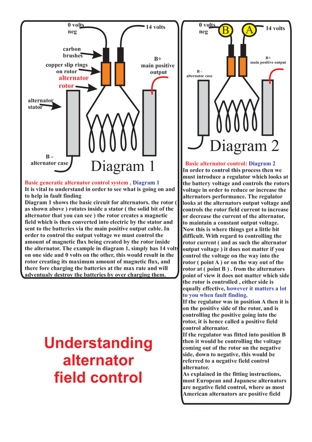
Basic generatic alternator control system , Diagram 1
It is vital to understand in order to see what is going on and to help in fault finding
Diagram 1 shows the basic circuit for alternators. the rotor ( as shown above ) rotates inside a stator ( the solid bit of the alternator that you can see ) the rotor creates a magnetic field which is then converted into electric by the stator and sent to the batteries via the main positive output cable. In order to control the output voltage we must control the amount of magnetic flux being created by the rotor inside the alternator. The example in diagram 1, simply has 14 volts on one side and 0 volts on the other, this would result in the rotor creating its maximum amount of magnetic flux, and there fore charging the batteries at the max rate and will adventualy destroy the batteries by over charging them.
Understanding
alternator
field control
Basic alternator control: Diagram 2 In order to control this process then we must introduce a regulator which looks at the battery voltage and controls the rotors voltage in order to reduce or increase the alternators performance. The regulator looks at the alternators output voltage and controls the rotor field current to increase or decrease the current of the alternator, to maintain a constant output voltage. Now this is where things get a little bit difficult. With regard to controlling the rotor current ( and as such the alternator output voltage ) it does not matter if you control the voltage on the way into the rotor ( point A ) or on the way out of the rotor at ( point B ) . from the alternators point of view it does not matter which side the rotor is controlled , either side is equally effective, however it matters a lot to you when fault finding.
If the regulator was in position A then it is on the positive side of the rotor, and is controlling the positive going into the rotor, it is hence called a positive field control alternator.
If the regulator was fitted into position B then it would be controlling the voltage coming out of the rotor on the negative side, down to negative, this would be referred to a negative field control alternator.
As explained in the fitting instructions, most European and Japanese alternators are negative field control, where as most American alternators are positive field