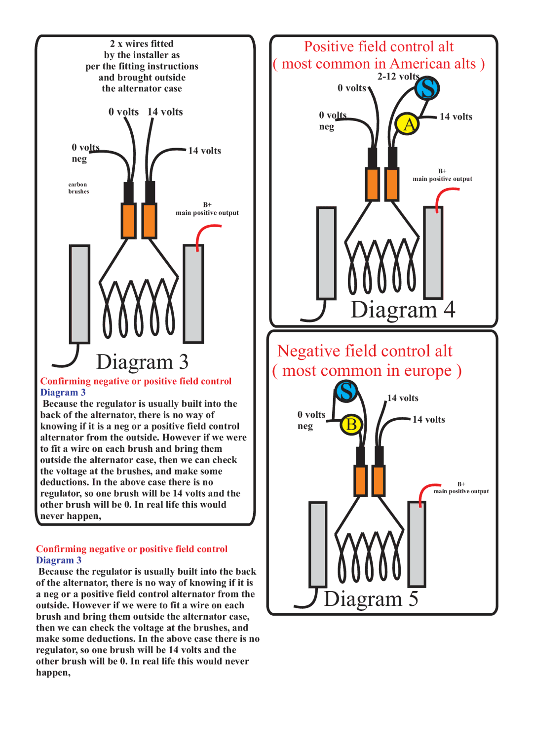
2 x wires fitted | Positive field control alt | |||||||||
by the installer as | ( most common in American alts ) | |||||||||
per the fitting instructions | ||||||||||
and brought outside |
|
|
| |||||||
the alternator case | 0 volts |
|
|
|
|
|
| s | ||
|
|
|
|
|
|
| ||||
0 volts | 14 volts | 0 volts |
|
|
|
|
|
| 14 volts | |
|
| neg |
|
|
|
|
|
| A | |
0 volts | 14 volts |
|
|
|
|
|
|
|
|
|
neg |
|
|
|
|
|
|
|
|
|
|
carbon
brushes
B+
main positive output
B+
main positive output
Diagram 4
Diagram 3
Confirming negative or positive field control Diagram 3
Because the regulator is usually built into the back of the alternator, there is no way of knowing if it is a neg or a positive field control alternator from the outside. However if we were to fit a wire on each brush and bring them outside the alternator case, then we can check the voltage at the brushes, and make some deductions. In the above case there is no regulator, so one brush will be 14 volts and the other brush will be 0. In real life this would never happen,
Negative field control alt
( most common in europe )
s 14 volts
0 volts
14 volts
neg B
B+
main positive output