EQUALIZING TIME CYCLE:
The software in the new Digital Regulator automatically calculates the equalizing time cycle every time the engine is started. This will range between
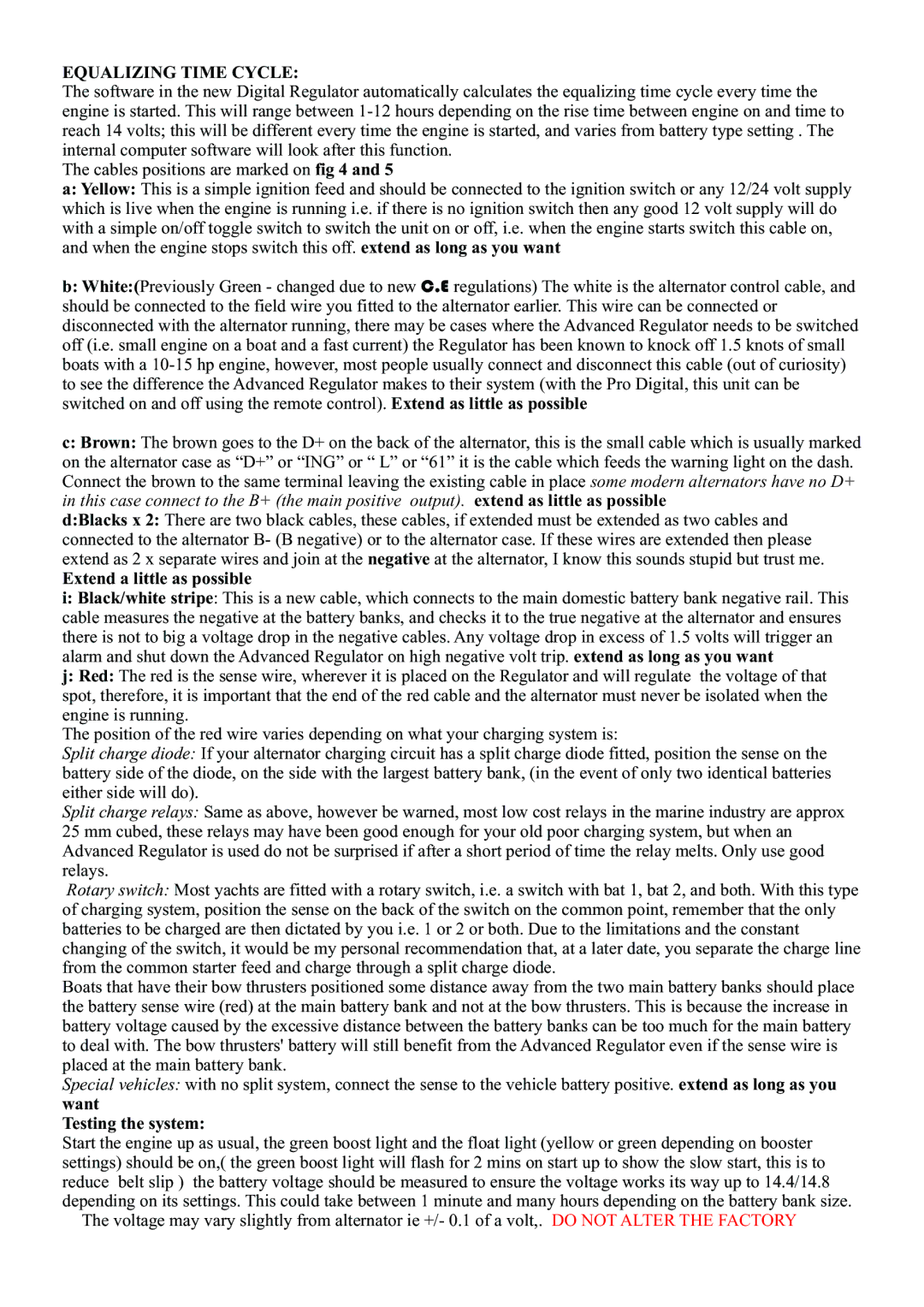
The cables positions are marked on fig 4 and 5
a:Yellow: This is a simple ignition feed and should be connected to the ignition switch or any 12/24 volt supply which is live when the engine is running i.e. if there is no ignition switch then any good 12 volt supply will do with a simple on/off toggle switch to switch the unit on or off, i.e. when the engine starts switch this cable on, and when the engine stops switch this off. extend as long as you want
b:White:(Previously Green - changed due to new C.E regulations) The white is the alternator control cable, and should be connected to the field wire you fitted to the alternator earlier. This wire can be connected or disconnected with the alternator running, there may be cases where the Advanced Regulator needs to be switched off (i.e. small engine on a boat and a fast current) the Regulator has been known to knock off 1.5 knots of small boats with a
c:Brown: The brown goes to the D+ on the back of the alternator, this is the small cable which is usually marked on the alternator case as “D+” or “ING” or “ L” or “61” it is the cable which feeds the warning light on the dash. Connect the brown to the same terminal leaving the existing cable in place some modern alternators have no D+ in this case connect to the B+ (the main positive output). extend as little as possible
d:Blacks x 2: There are two black cables, these cables, if extended must be extended as two cables and connected to the alternator B- (B negative) or to the alternator case. If these wires are extended then please extend as 2 x separate wires and join at the negative at the alternator, I know this sounds stupid but trust me.
Extend a little as possible
i:Black/white stripe: This is a new cable, which connects to the main domestic battery bank negative rail. This cable measures the negative at the battery banks, and checks it to the true negative at the alternator and ensures there is not to big a voltage drop in the negative cables. Any voltage drop in excess of 1.5 volts will trigger an alarm and shut down the Advanced Regulator on high negative volt trip. extend as long as you want
j:Red: The red is the sense wire, wherever it is placed on the Regulator and will regulate the voltage of that spot, therefore, it is important that the end of the red cable and the alternator must never be isolated when the engine is running.
The position of the red wire varies depending on what your charging system is:
Split charge diode: If your alternator charging circuit has a split charge diode fitted, position the sense on the battery side of the diode, on the side with the largest battery bank, (in the event of only two identical batteries either side will do).
Split charge relays: Same as above, however be warned, most low cost relays in the marine industry are approx 25 mm cubed, these relays may have been good enough for your old poor charging system, but when an Advanced Regulator is used do not be surprised if after a short period of time the relay melts. Only use good relays.
Rotary switch: Most yachts are fitted with a rotary switch, i.e. a switch with bat 1, bat 2, and both. With this type of charging system, position the sense on the back of the switch on the common point, remember that the only batteries to be charged are then dictated by you i.e. 1 or 2 or both. Due to the limitations and the constant changing of the switch, it would be my personal recommendation that, at a later date, you separate the charge line from the common starter feed and charge through a split charge diode.
Boats that have their bow thrusters positioned some distance away from the two main battery banks should place the battery sense wire (red) at the main battery bank and not at the bow thrusters. This is because the increase in battery voltage caused by the excessive distance between the battery banks can be too much for the main battery to deal with. The bow thrusters' battery will still benefit from the Advanced Regulator even if the sense wire is placed at the main battery bank.
Special vehicles: with no split system, connect the sense to the vehicle battery positive. extend as long as you
want
Testing the system:
Start the engine up as usual, the green boost light and the float light (yellow or green depending on booster settings) should be on,( the green boost light will flash for 2 mins on start up to show the slow start, this is to reduce belt slip ) the battery voltage should be measured to ensure the voltage works its way up to 14.4/14.8 depending on its settings. This could take between 1 minute and many hours depending on the battery bank size.
The voltage may vary slightly from alternator ie +/- 0.1 of a volt,. DO NOT ALTER THE FACTORY