SERVICING INSTRUCTIONS
REPLACING PARTS
5.MAGNETIC UNIT
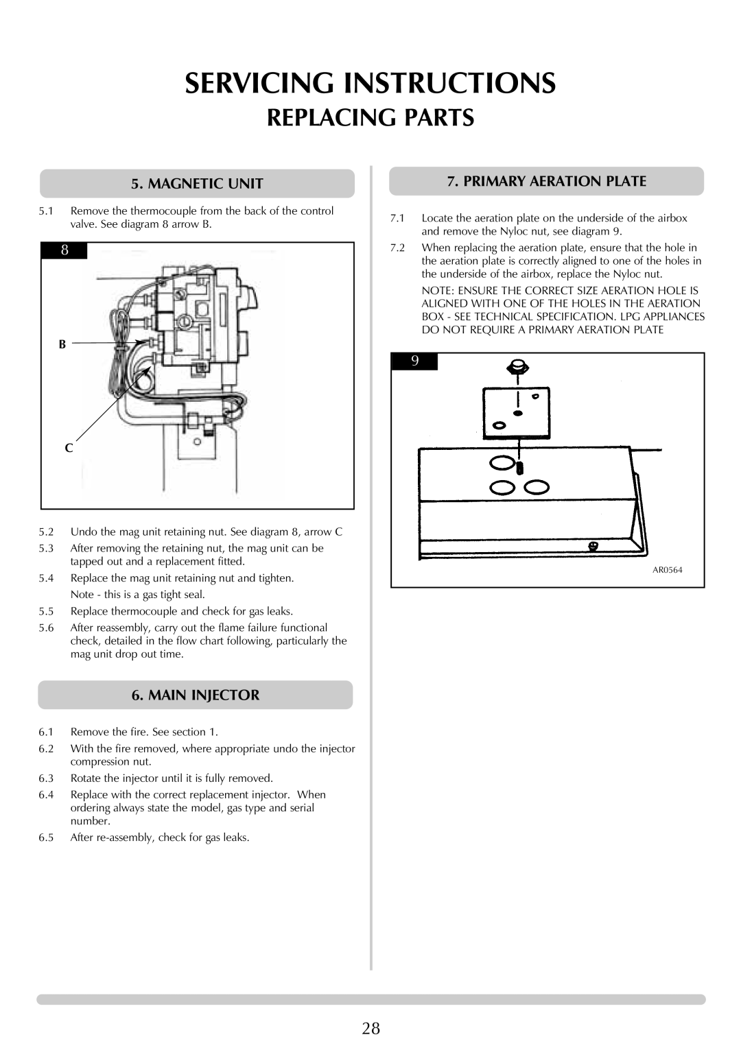
5.1Remove the thermocouple from the back of the control valve. See diagram 8 arrow B.
8
B ![]()
C
5.2Undo the mag unit retaining nut. See diagram 8, arrow C
5.3After removing the retaining nut, the mag unit can be tapped out and a replacement fitted.
5.4Replace the mag unit retaining nut and tighten. Note - this is a gas tight seal.
5.5Replace thermocouple and check for gas leaks.
5.6After reassembly, carry out the flame failure functional check, detailed in the flow chart following, particularly the mag unit drop out time.
6.MAIN INJECTOR
6.1Remove the fire. See section 1.
6.2With the fire removed, where appropriate undo the injector compression nut.
6.3Rotate the injector until it is fully removed.
6.4Replace with the correct replacement injector. When ordering always state the model, gas type and serial number.
6.5After
7.PRIMARY AERATION PLATE
7.1Locate the aeration plate on the underside of the airbox and remove the Nyloc nut, see diagram 9.
7.2When replacing the aeration plate, ensure that the hole in the aeration plate is correctly aligned to one of the holes in the underside of the airbox, replace the Nyloc nut.
NOTE: ENSURE THE CORRECT SIZE AERATION HOLE IS ALIGNED WITH ONE OF THE HOLES IN THE AERATION BOX - SEE TECHNICAL SPECIFICATION. LPG APPLIANCES DO NOT REQUIRE A PRIMARY AERATION PLATE
9
AR0564
28