Safety Information and Technical Specifications
3-3 Front Jumper Locations and Pin Definitions
|
| A18 | JSM2 | A1 |
|
| MH1 |
|
|
| JP61 |
|
|
|
|
|
| ||
|
|
| ||
JP61 | 1 |
|
|
|
3 | JP61 |
| Y2 | |
|
| B18 SAS IN | B1 | |
|
| JP54 |
|
|
|
| 1 FAN |
|
|
44 | 34 UPGRADE #2 | 6 | UPGRADE #1 | 22 | 12 |
| A18 | JSM1 | A1 | |
|
| 523 |
|
|
|
|
|
|
| |
| 1 | 2 |
|
|
|
|
|
|
| |
|
| JP47 | JP46 |
|
|
|
|
|
| MH2 |
| 5 | 62 | 1 |
|
|
|
|
|
|
|
|
|
|
|
|
|
|
|
|
| |
|
|
| 33 |
|
|
|
|
|
|
|
| 23 |
|
|
|
|
| Y1 |
|
|
|
|
|
|
|
|
|
|
|
|
| |
|
|
|
| 34 | U40 | 44 | B18 | SAS IN | B1 | |
|
|
|
|
|
|
| RP14 |
|
|
|
|
|
| TP4 TP3 |
|
|
|
|
|
|
|
|
|
| ACT LED TEST |
|
|
|
|
|
|
|
| JP62 |
|
|
|
|
|
|
|
|
|
JP3
1
DESIGNED IN USA
4
JP25: OH![]()
![]() TEMP OPEN 45 C
TEMP OPEN 45 C
ARB CODE
| + | JP62 |
| + |
|
|
| |
| 3 | 1 |
|
| + |
| ||
|
|
|
|
|
| |||
|
|
|
| JP25 |
|
|
| |
C84 | JP25 | 1 | C78 |
| 1 | 4 | ||
R69 |
| 3 |
|
|
|
|
|
|
|
|
|
| C77 | +12V JP1 | +5V | ||
|
|
| 9071 RST |
| REV 1.00 |
| ||
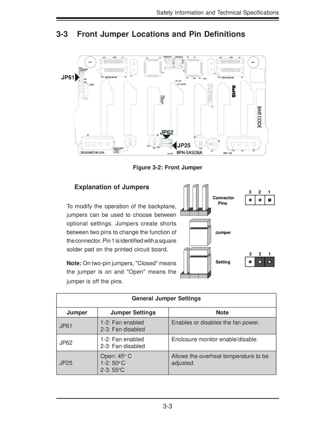
Figure 3-2: Front Jumper
Explanation of Jumpers
To modify the operation of the backplane, jumpers can be used to choose between optional settings. Jumpers create shorts between two pins to change the function of the connector. Pin 1 is identified with a square solder pad on the printed circuit board.
Note: On
3 2 1
Connector
Pins
Jumper
3 2 1
Setting
General Jumper Settings
Jumper | Jumper Settings | Note |
JP61 | Enables or disables the fan power. | |
| ||
|
| |
JP62 | Enclosure monitor enable/disable. | |
| ||
|
| |
JP25 | Open: 45o C | Allows the overheat temperature to be |
adjusted. | ||
|
|