X6DH3-G2/X6DHi-G2 User's Manual

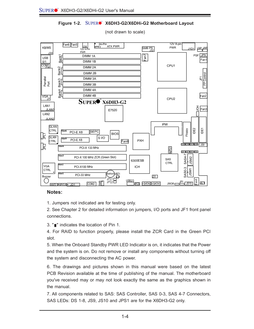
Figure 1-2. X6DH3-G2/X6DHi-G2 Motherboard Layout

(not drawn to scale)

KB/MS J33

USB 0/1


Fan6


Fan5


J38


24-Pin

ATX PWR


JPW1


12V 4-Pin


PWR


Bank1


DIMM 1B


DIMM 1A


SMB PS J32

n7 Fa

12V 8-pin

PWR

J1D1

J3P JAR


PSF

JP9


Fan1

COM1 J14

ParrallelJLAN1Port

VGA J7

Bank2

Bank3

Bank4

DIMM 2A

DIMM 2B

DIMM 3A

DIMM 3B

DIMM 4A

DIMM 4B

SUPER

®

X6DH3-G2

CPU1

JF1

FPControl

Fan2

CPU2

LAN1 JLAN1

LAN2 JLAN2

E7520

JOH

Fan3


IPMI


GLAN


CTRL


Slot6


JPL1


PCI-E X8

SEPC


BIOS


Slot5


S I/O


GLAN


JPL2

CTRL


PCI-E X8


Fan8

PXH


Slot4

PCI-X 133 MHz


Floppy

IDE2

IDE1


DS5 DS6

DS7

DS8

JS9

S1JP


DS1

DS2

DS3

DS4


Slot3

PCI-X 100 MHz ZCR (Green Slot)


Slot2


VGA


PCI-X100 MHz


CTRL


Slot1


Battery


Buzzer


PCI-33 MHz


JBT1


2


SMB


JI C1


2


COM2


JI C2


JWD

JPG1

JD1


6300ESB ICH

J31

USB2/3

WOL

I-SATA0

I-SATA1


-7


SAS

SAS4


JSM2


CTRL


SAS0-3


JSM1

Fan4


JWOR

JP1

JS10

JL1


Notes:

1.Jumpers not indicated are for testing only.

2.See Chapter 2 for detailed information on jumpers, I/O ports and JF1 front panel connections.

3." " indicates the location of Pin 1.

4.For RAID to function properly, please install the ZCR Card in the Green PCI slot.

5.When the Onboard Standby PWR LED Indicator is on, it indicates that the Power and the system is on. Do not remove or install any components without turning off the system and disconnecting the AC power.

6.The drawings and pictures shown in this manual were based on the latest PCB Revision available at the time of publishing of the manual. The motherboard you've received may or may not look exactly the same as the graphics shown in the manual.

7.All components related to SAS: SAS Controller, SAS 0-3, SAS 4-7 Connectors, SAS LEDs: DS 1-8, JS9, JS10 and JPS1 are for the X6DH3-G2 only.

1-4

Page 10
Image 10
SUPER MICRO Computer X6DHi-G2, X6DH3-G2 user manual Super

X6DH3-G2, X6DHi-G2 specifications

Super Micro Computer is renowned for its innovation in the server and workstation market, and the X6DH3-G2 and X6DHi-G2 motherboards are prime examples of their commitment to performance, reliability, and advanced technology. These motherboards are designed to cater to the demands of enterprise-level applications, offering robust support for a variety of workloads.

The X6DH3-G2 and X6DHi-G2 motherboards are based on the Intel E7501 chipset, supporting the Intel Xeon processor family. This allows for significant computing power, making them ideal choices for data-centric applications in various fields, from scientific research to database management. One of the standout features of these motherboards is their dual-processor capability, enabling users to harness the power of two Xeon CPUs simultaneously for enhanced multitasking and performance.

In addition to dual-processor support, both motherboards offer up to 64 GB of DDR2 ECC memory. This ensures data integrity and system stability, which are crucial in enterprise environments. The presence of ECC (Error-Correcting Code) memory allows these motherboards to automatically detect and correct data corruption, significantly reducing the risk of system crashes and data loss.

Storage capabilities are another highlight of the X6DH3-G2 and X6DHi-G2 motherboards. They come equipped with multiple SATA and SCSI interfaces, ensuring compatibility with various storage solutions. This flexibility allows users to configure their storage according to their specific needs, whether it be for high-speed access or large-capacity requirements. RAID (Redundant Array of Independent Disks) support is also integrated, enabling users to implement data redundancy and improve performance.

Networking features are robust, with integrated gigabit Ethernet that ensures high-speed connections and efficient data transfer. This is essential for applications demanding low latency and high bandwidth.

The layout of the X6DH3-G2 and X6DHi-G2 motherboards is designed for optimal thermal management and airflow, enhancing system longevity and reliability. They also support a range of expansion slots, including PCI Express, which allows for the addition of graphics cards and other advanced peripherals.

Super Micro’s commitment to quality is evident in these motherboards, showcasing reliability and a wealth of features that make them suitable for demanding enterprise environments. With a focus on performance, scalability, and stability, the X6DH3-G2 and X6DHi-G2 motherboards are engineered to meet the evolving challenges faced by IT professionals and organizations today.