
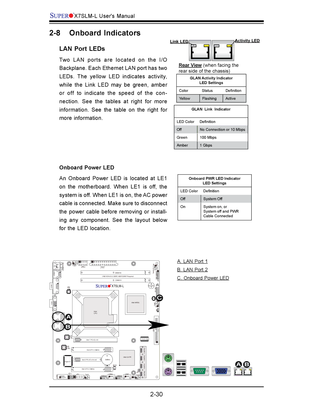
x7slm-l specifications
Super Micro Computer Inc., commonly known as Supermicro, has been a prominent player in the server and high-performance computing markets. Among its extensive product range, the X7SLM-L motherboard stands out as an ideal solution for both server and workstation applications. Equipped with cutting-edge technology, the X7SLM-L caters to a variety of user demands, including scalability, reliability, and compatibility.The Supermicro X7SLM-L motherboard is built on an Intel Socket 775 platform, offering support for multi-core Intel processors, including the Xeon series. This enables users to harness the processing power necessary for demanding applications like virtualization, database management, and scientific computations. The board can accommodate up to 8 GB of DDR2 memory, which is essential for memory-intensive tasks, ensuring smooth and efficient performance.
One of the standout features of the X7SLM-L is its support for PCI Express 2.0, allowing for enhanced graphics and expansion capabilities. Users can easily integrate high-performance add-on cards, which are crucial for fields such as video editing, gaming, and CAD applications. Furthermore, the motherboard comes with multiple SATA ports, offering exceptional flexibility for storage configurations. With support for RAID levels 0, 1, 5, and 10, users can ensure data protection and improve performance.
Another important characteristic of the X7SLM-L is its embedded network controller, which provides high-speed connectivity options to meet the needs of data center environments. With integrated dual Gigabit Ethernet, users can take advantage of redundancy and load balancing, crucial for maintaining uptime in critical applications.
Supermicro's commitment to energy efficiency is also evident in the X7SLM-L design. The motherboard supports Intel’s SpeedStep technology, providing dynamic adjustment of CPU voltage and frequency according to workload requirements, thus reducing power consumption and heat generation.
In summary, the Supermicro X7SLM-L motherboard is a versatile and feature-rich platform designed for users who require high performance and reliability. With support for advanced Intel processors, substantial memory capacity, flexible storage options, and energy-efficient technologies, the X7SLM-L stands as an excellent choice for a wide range of computing applications. Whether for server deployments or demanding workstation tasks, this motherboard provides a solid foundation for next-generation computing needs.