SUPER MICRO Computer X7DBT-INF, XDGT, X7DGT-INF user manual Hdd Led, NIC1/NIC2 LED Indicators

Models: X7DBT X7DBT-INF XDGT X7DGT-INF

1 122
Download 122 pages 43.97 Kb
Page 31
Image 31

Chapter 2: Installation

HDD LED

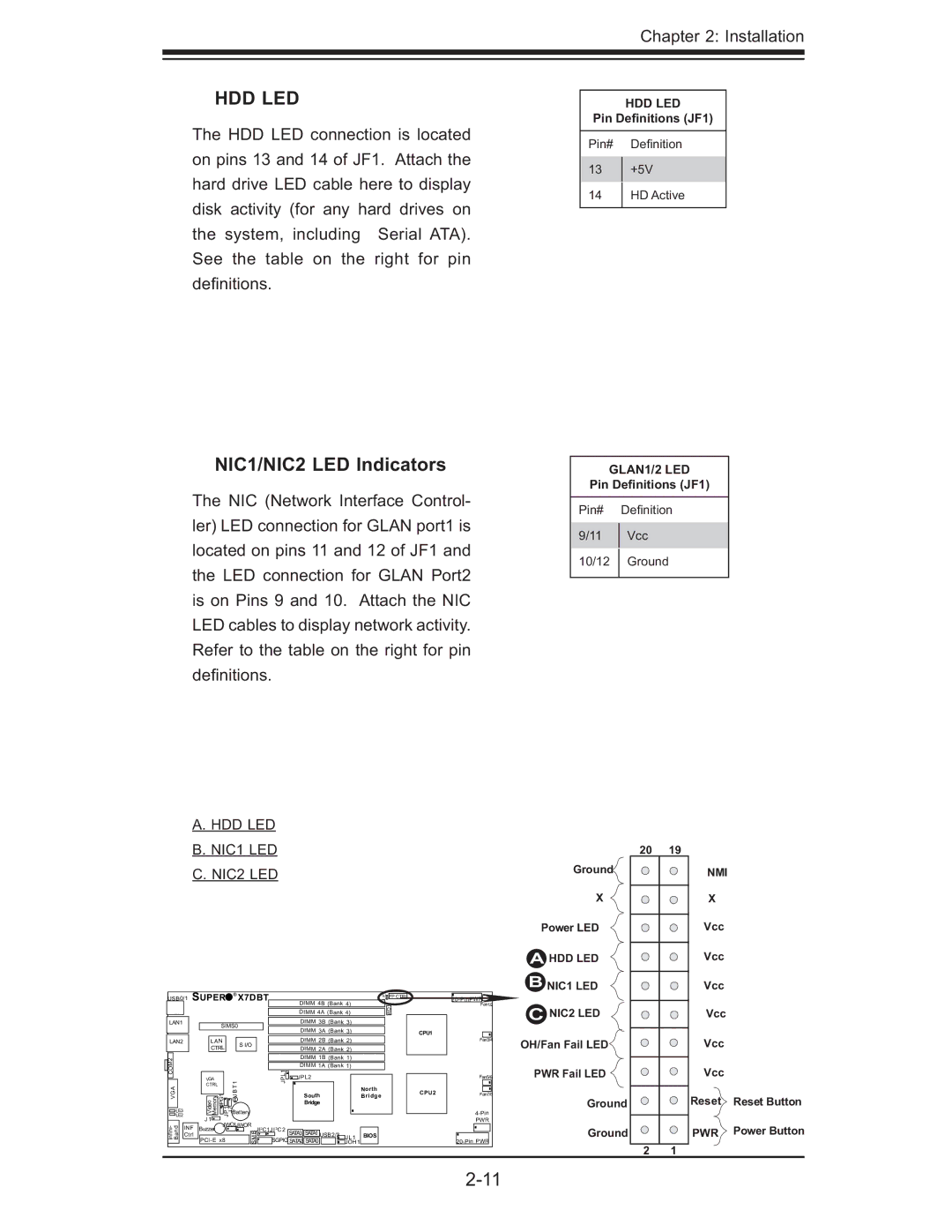
The HDD LED connection is located on pins 13 and 14 of JF1. Attach the hard drive LED cable here to display disk activity (for any hard drives on the system, including Serial ATA). See the table on the right for pin defi nitions.

NIC1/NIC2 LED Indicators

The NIC (Network Interface Control- ler) LED connection for GLAN port1 is located on pins 11 and 12 of JF1 and the LED connection for GLAN Port2 is on Pins 9 and 10. Attach the NIC LED cables to display network activity. Refer to the table on the right for pin defi nitions.

HDD LED

Pin Definitions (JF1)

Pin# Defi nition

13+5V

14HD Active

GLAN1/2 LED

Pin Definitions (JF1)

Pin#

Defi nition

9/11

Vcc

10/12

Ground


A. HDD LED


B. NIC1 LED


20

19


C. NIC2 LED


Ground

NMI


X

X


Power LED

Vcc


A HDD LED

Vcc


SUPER

®

X7DBT


LE1


B NIC1 LED

Vcc


USB0/1


FP CTRL

20-PinPWR


DIMM 4B (Bank 4)


LAN1


WD

Fan1/2

C NIC2 LED

Vcc


DIMM

3B

(Bank 3)


DIMM 4A

(Bank 4)


SIMS0


DIMM 3A (Bank 3)


CPU1


LAN2


LAN


S I/O


DIMM 2B (Bank 2)


Fan3/4

OH/Fan Fail LED

Vcc


CTRL


DIMM 2A (Bank 2)


COM2


DIMM 1B (Bank 1)


JPL1

DIMM 1A (Bank 1)


Vcc


VGA


1


JPL2


Fan5/6

PWR Fail LED


VGA


CTRL


T


BJ


South


Bridge


CPU2

Fan7/8


PG1


North


LE2


VideoMemory

JP1 Battery


Bridge


4-Pin

Ground

Reset

Reset Button


J


LE3


7


J


J 1

JWOLJWOR


PWR


-

INF


2


2


Infini Band

Buzzer


B


SATA3 SATA1


Power Button

Ctrl


JI

C1JI C2

USB2/3 JL1

BIOS


Ground

PWR


PCI-E x8


M


20-Pin PWR


S


SGPIO SATA2 SATA0

JOH1


2

1


2-11


Page 31
Image 31
SUPER MICRO Computer X7DBT-INF, XDGT, X7DGT-INF user manual Hdd Led, NIC1/NIC2 LED Indicators

X7DBT, X7DBT-INF, XDGT, X7DGT-INF specifications

Super Micro Computer, a leader in high-performance computing solutions, offers a diverse range of server motherboards tailored for various business needs. Among these, the Supermicro X7DGT-INF, X7DGT, X7DBT-INF, and X7DBT stand out for their robust architectures and advanced features.

The Supermicro X7DGT-INF motherboard is designed for dual processor systems utilizing Intel's Xeon processors. It supports up to 64GB of DDR2 memory, providing significant flexibility for memory-intensive applications. The X7DGT-INF features six SATA ports, enabling efficient data storage solutions with RAID configurations. Additionally, it offers integrated IPMI (Intelligent Platform Management Interface) functionality, which allows remote management of the motherboard, enhancing system uptime and reliability.

The X7DGT shares many features with the INF model but enhances connectivity options with PCI Express slots, making it ideal for virtualization and embedded applications. This dual-CPU motherboard allows for up to 128GB of memory, catering to businesses that require high computational power and substantial memory bandwidth, particularly for tasks such as data analysis and enterprise resource planning.

Meanwhile, the Supermicro X7DBT-INF is notable for its dual-broadband capabilities, which facilitate high throughput for networking tasks. Like its siblings, it supports Intel Xeon processors and DDR2 memory but goes a step further with onboard dual Gigabit Ethernet and a dedicated IPMI controller. Its design emphasizes optimal thermal management, ensuring that power-hungry applications remain stable under heavy workloads.

The X7DBT also supports dual processors and provides a robust memory architecture. It is engineered for high-performance computing environments. Featuring multiple PCI Express slots, this motherboard is ideal for applications such as cluster computing and high-frequency trading where low latency and high-speed networking are essential.

Overall, the Supermicro X7DGT-INF, X7DGT, X7DBT-INF, and X7DBT motherboards epitomize reliability and performance. Their compatibility with Intel’s Xeon processors, extensive memory options, and advanced connectivity features make them superb choices for enterprise-level applications, data centers, and research institutions that demand uncompromising performance and efficiency in their computing solutions.