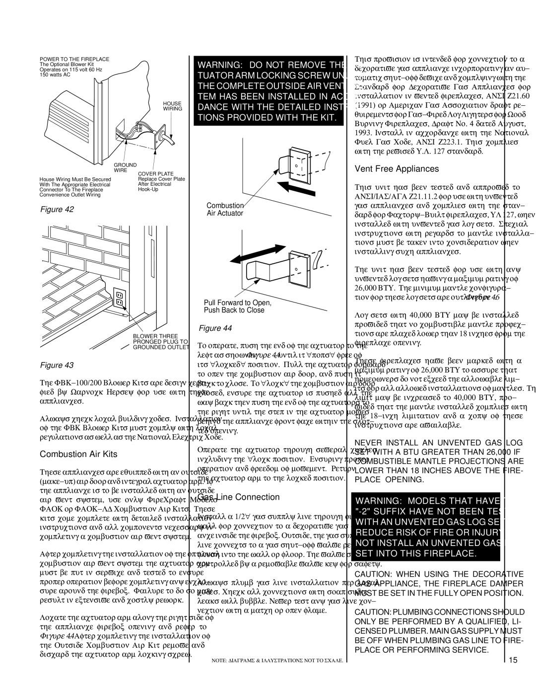
POWER TO THE FIREPLACE The Optional Blower Kit Operates on 115 volt 60 Hz 150 watts AC
HOUSE
WIRING
| GROUND |
| WIRE |
| COVER PLATE |
House Wiring Must Be Secured | Replace Cover Plate |
With The Appropriate Electrical | After Electrical |
Connector To The Fireplace | |
Convenience Outlet Wiring |
|
Figure 42
BLOWER THREE
PRONGED PLUG TO
GROUNDED OUTLET
Figure 43
The
Always check local building codes. Installation of the FBK Blower Kits must comply with local regulations as well as the National Electric Code.
Combustion Air Kits
These appliances are equipped with an outside
After completing the installation of the optional combustion air vent system the actuator arm must be put in service and tested to ensure proper operation before completing any enclo- sure around the firebox. Failure to do so may result in extensive and costly rework.
Locate the actuator arm along the right side of the appliance firebox opening and refer to Figure 44. After completing the installation of the Outside Combustion Air Kit remove and discard the actuator arm locking screw.
WARNING: DO NOT REMOVE THE AC- TUATOR ARM LOCKING SCREW UNLESS THE COMPLETE OUTSIDE AIR VENT SYS- TEM HAS BEEN INSTALLED IN ACCOR- DANCE WITH THE DETAILED INSTRUC- TIONS PROVIDED WITH THE KIT.
Combustion
Air Actuator
Pull Forward to Open,
Push Back to Close
Figure 44
To operate, push the end of the actuator to the left as shown in Figure 44, until it "pops" free of its "locked" position. Pull the actuator forward to open the combustion air door, and push it back to close. To "lock" the combustion air door closed, ensure the actuator is pushed all the way back then push the end of the actuators to the right until the step in the actuator moves behind the appliance front face within the slot- ted opening.
Operate the actuator through several cycles including the "lock position. Ensuring proper operation and freedom of movement. Return the actuator arm to the locked position.
Gas Line Connection
Install a 1/2" gas supply line through fireplace wall for connection to a decorative gas appli- ance inside the firebox. Outside, the gas supply line connects to a gas
Always plumb gas line installation per local codes. Check all connections with soap suds; leaks will bubble. Never test any gas line con- nection with a match or open flame.
NOTE: DIAGRAMS & ILLUSTRATIONS NOT TO SCALE.
This provision is intended for connection to a decorative gas appliance incorporating an au- tomatic
Vent Free Appliances
This unit has been tested and approved to ANSI/IAS/AGA Z21.11.2 for use with unvented gas appliances and complies with the stan- dard for
The unit has been tested for use with any unvented log sets having a maximum rating of 26,000 BTU. The minimum mantle configura- tion for these log sets are outlined in Figure 46.
Log sets with 40,000 BTU may be installed provided that no combustible mantle projec- tions are placed lower than 18 inches from the fireplace opening.
These fireplaces have been marked with a maximum rating of 26,000 BTU to assure that homeowners do not exceed the allowable lim- its for all allowed installations of mantles. That limit may be increased to 40,000 BTU, pro- vided that the mantle installed complies with the
NEVER INSTALL AN UNVENTED GAS LOG SET WITH A BTU GREATER THAN 26,000 IF COMBUSTIBLE MANTLE PROJECTIONS ARE LOWER THAN 18 INCHES ABOVE THE FIRE- PLACE OPENING.
WARNING: MODELS THAT HAVE THE
CAUTION: WHEN USING THE DECORATIVE GAS APPLIANCE, THE FIREPLACE DAMPER MUST BE SET IN THE FULLY OPEN POSITION.
CAUTION: PLUMBING CONNECTIONS SHOULD ONLY BE PERFORMED BY A QUALIFIED, LI- CENSED PLUMBER. MAIN GAS SUPPLY MUST BE OFF WHEN PLUMBING GAS LINE TO FIRE- PLACE OR PERFORMING SERVICE.
15