Connection Diagram
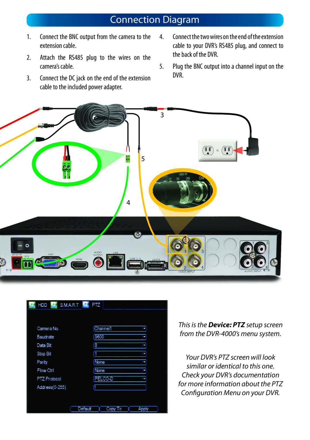
1. | Connect the BNC output from the camera to the | 4. | Connect the two wires on the end of the extension |
| extension cable. |
| cable to your DVR’s RS485 plug, and connect to |
2. | Attach the RS485 plug to the wires on the |
| the back of the DVR. |
|
| ||
| camera’s cable. | 5. | Plug the BNC output into a channel input on the |
3. | Connect the DC jack on the end of the extension |
| DVR. |
|
|
cable to the included power adapter.
3
5
4
This is the Device: PTZ setup screen from the
Your DVR’s PTZ screen will look similar or identical to this one.
Check your DVR’s documentation for more information about the PTZ Configuration Menu on your DVR.