System Sensor BS5839 manual Corridors, Corridor being 7.5m and 5.3m respectively, Sloping Ceilings

Models: BS5839

1 32
Download 32 pages 58.43 Kb
Page 14
Image 14

Guide

>10% of Ceiling Height

Treat as separate room

>250mm <10% of Ceiling Height

Minimum

500mm

Minimum

500mm

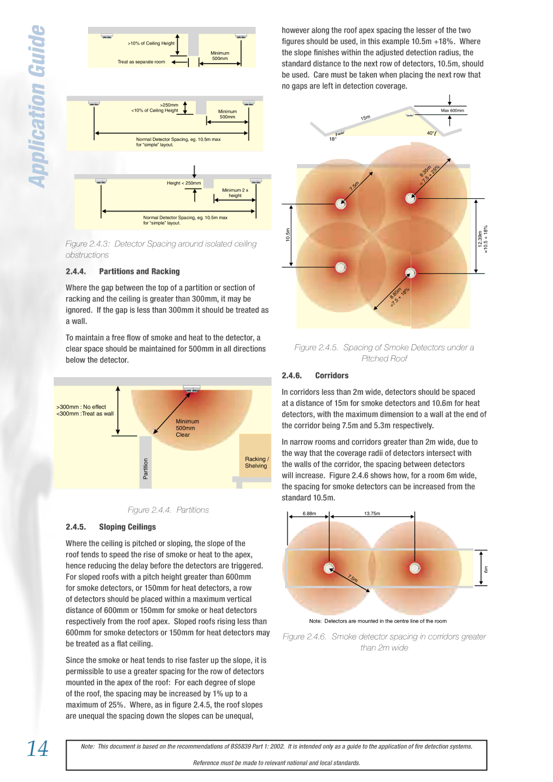
however along the roof apex spacing the lesser of the two figures should be used, in this example 10.5m +18%. Where the slope finishes within the adjusted detection radius, the standard distance to the next row of detectors, 10.5m, should be used. Care must be taken when placing the next row that no gaps are left in detection coverage.

Max 600mm

15m

Application

Normal Detector Spacing, eg. 10.5m max for “simple” layout.

Height < 250mm

Minimum 2 x

height


40°

18°


.35m 25%


9

+


.5

.5m

7

=


7


Normal Detector Spacing, eg. 10.5m max for “simple” layout.

Figure 2.4.3: Detector Spacing around isolated ceiling obstructions

2.4.4.Partitions and Racking

Where the gap between the top of a partition or section of racking and the ceiling is greater than 300mm, it may be ignored. If the gap is less than 300mm it should be treated as a wall.

To maintain a free flow of smoke and heat to the detector, a clear space should be maintained for 500mm in all directions below the detector.

>300mm : No effect <300mm :Treat as wall

10.5m


12.39m =10.5+18%

.85m

18%

8

+


.5


=7


Figure 2.4.5. Spacing of Smoke Detectors under a

Pitched Roof

2.4.6.Corridors

In corridors less than 2m wide, detectors should be spaced at a distance of 15m for smoke detectors and 10.6m for heat detectors, with the maximum dimension to a wall at the end of

Minimum 500mm Clear

Partition

Racking / Shelving

the corridor being 7.5m and 5.3m respectively.

In narrow rooms and corridors greater than 2m wide, due to the way that the coverage radii of detectors intersect with the walls of the corridor, the spacing between detectors will increase. Figure 2.4.6 shows how, for a room 6m wide, the spacing for smoke detectors can be increased from the standard 10.5m.

Figure 2.4.4. Partitions

2.4.5.Sloping Ceilings

Where the ceiling is pitched or sloping, the slope of the roof tends to speed the rise of smoke or heat to the apex, hence reducing the delay before the detectors are triggered. For sloped roofs with a pitch height greater than 600mm for smoke detectors, or 150mm for heat detectors, a row of detectors should be placed within a maximum vertical distance of 600mm or 150mm for smoke or heat detectors respectively from the roof apex. Sloped roofs rising less than 600mm for smoke detectors or 150mm for heat detectors may be treated as a flat ceiling.

Since the smoke or heat tends to rise faster up the slope, it is permissible to use a greater spacing for the row of detectors mounted in the apex of the roof: For each degree of slope of the roof, the spacing may be increased by 1% up to a maximum of 25%. Where, as in figure 2.4.5, the roof slopes are unequal the spacing down the slopes can be unequal,

6.88m13.75m

6m

7.5m

Note: Detectors are mounted in the centre line of the room

Figure 2.4.6. Smoke detector spacing in corridors greater

than 2m wide

14

Note: This document is based on the recommendations of BS5839 Part 1: 2002. It is intended only as a guide to the application of fire detection systems.

Reference must be made to relevant national and local standards.

Page 14
Image 14
System Sensor BS5839 manual Corridors, Corridor being 7.5m and 5.3m respectively, Sloping Ceilings

BS5839 specifications

System Sensor BS5839 is a standard that pertains to fire detection and alarm systems, providing guidelines for the design, installation, and maintenance of these essential safety tools. It is crucial for safeguarding lives and property, ensuring that fire detection systems are effective and reliable. The BS5839 standard, established in the UK, covers a wide range of fire alarm system types, including conventional, addressable, and wireless systems.

One of the main features of BS5839 is its comprehensive classification of fire detection systems. The standard divides systems into categories based on the level of risk and the environment in which the system will operate. This classification helps ensure that the system installed meets the specific needs of the building and its occupants. For example, Category L systems are meant for life safety, while Category P systems are designed to protect property.

The technologies underpinning BS5839 include various types of detectors, alarm devices, and control panels. Smoke detectors, heat detectors, and multi-sensor detectors are prominent among the devices specified in the standard. Smoke detectors use photoelectric or ionization principles to detect smoke and signal an alarm, while heat detectors respond to temperature changes. Multi-sensor detectors combine both smoke and heat detection technologies to provide a more reliable response to fire conditions.

Another key characteristic of BS5839 is the emphasis on regular testing and maintenance. The standard outlines procedures to ensure that systems remain operational and effective over time. This includes routine system checks, functional testing, and more in-depth inspections at regular intervals. Ensuring that systems are maintained according to BS5839 is vital for compliance with insurance requirements and for safeguarding against potential legal liabilities.

Furthermore, BS5839 highlights the importance of staff training and awareness. It emphasizes that personnel responsible for fire safety must be adequately trained in the operation and response to fire alarm systems. This ensures that in the event of a fire, occupants are prompted to take appropriate action and evacuate safely.

In summary, System Sensor BS5839 provides a crucial framework for fire detection and alarm systems. Its classification of systems, incorporation of advanced technologies, and emphasis on maintenance all contribute to enhanced safety and compliance, protecting lives and property effectively.