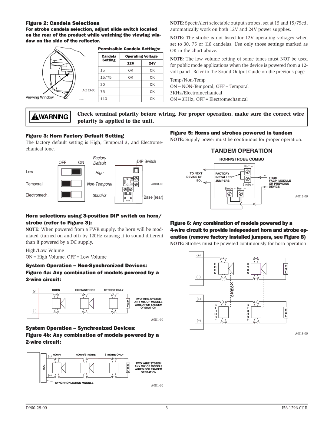
S1224MC specifications
The System Sensor S1224MC is a highly advanced smoke detector designed for commercial and industrial applications. It offers an array of features and technologies that ensure effective fire detection and reliable performance in various environments. This product exemplifies System Sensor's commitment to innovation and safety, making it a popular choice among fire safety professionals.One of the main features of the S1224MC is its intelligent optical sensing technology. This advanced sensing mechanism allows the detector to differentiate between false alarms and real fire conditions with remarkable accuracy. The optical sensor is particularly effective in detecting smoldering fires that produce larger particles, thus providing early warning and minimizing the risk of extensive damage.
The S1224MC also incorporates a unique dual-sensor design which enhances its detection capabilities. This design combines an optical sensor with a heat sensor, allowing for a broader range of fire types to be detected. The dual-sensor approach not only improves response times but also reduces the chances of nuisance alarms, a common issue in many environments.
Another significant characteristic of the S1224MC is its built-in digital display. This feature provides real-time information about the detector’s operational status, including sensitivity levels and battery health. Users can easily monitor this information, enabling timely maintenance and ensuring optimal performance.
Compatibility is also a strong suit of the S1224MC, as it is designed to seamlessly integrate with existing fire alarm systems. The device can be connected to a wide array of control panels and is compatible with various communication protocols, enhancing its versatility. This adaptability makes it suitable for installation in diverse settings, from educational institutions to commercial buildings.
The S1224MC’s design emphasizes durability and robustness. Constructed from high-quality materials, it can withstand harsh environmental conditions, making it suitable for both indoor and outdoor applications. Furthermore, the unit has a long operational life, supported by low power consumption, thus minimizing maintenance costs.
In conclusion, the System Sensor S1224MC combines state-of-the-art features and technologies to provide reliable fire protection in a variety of environments. Its intelligent sensor technology, dual-sensor design, real-time monitoring capabilities, and compatibility with various systems make it an essential component of modern fire safety solutions. Whether for new installations or upgrades, the S1224MC stands out as a premier choice for professionals seeking reliability and performance in fire detection.

