If the source itself has a balanced output, use shielded twin conductor cable (microphone cable) connecting pin 2/T to pin 2/T, pin 3/R to pin 3/R, and pin 1/S to pin 1/S (using the shield).
If the source has an unbalanced output, a single conductor shielded cable can be used, connecting pin 2/T of the input to the “hot” signal pin of the source, while pin 3/R and pin 1/S should be linked together and connected to the source signal ground.
Controls and indicators.
The input level switch (location 5) provides a sensitivity (i.e. gain) adjustment, the top and bottom positions corresponding respectively to
When set to ‘Free space’, the LF Contour facility (location 6) extends the bass response and enhances the low frequency content below 150 Hz by means of a
The HF Contour switch (location 7) allows adjustment of the HF level. Its operates as a shelving filter above 2 kHz with
Use close to TV screens and video monitors.
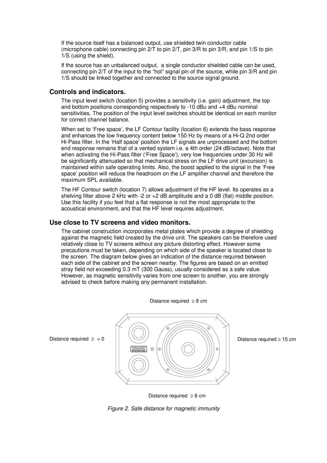
The cabinet construction incorporates metal plates which provide a degree of shielding against the magnetic field created by the drive unit. The speakers can be therefore used relatively close to TV screens without any picture distorting effect. However some precautions must be taken, depending on which side of the speaker is located close to the screen. The diagram below gives an indication of the distance required between each side of the cabinet and the screen nearby. The figures are based on an emitted stray field not exceeding 0.3 mT (300 Gauss), usually considered as a safe value. However, as magnetic sensitivity varies from one screen to another, you are strongly advised to check before making any permanent installation.
Distance required ≥ 8 cm
Distance required ≥ = 0
Distance required ≥ 15 cm
Distance required ≥ 8 cm
