![]()
![]()
![]() 21
21
MECHANICAL INSTALLATION 110CS
1)At your desired location, establish a “bottom” mark in the corner. For a minimum recommended space of 6” between the top of the subwoofer and the ceiling (to access the connector panel), this mark should fall at least 20” from the ceiling. Extend a 20” level, horizontal pencil line on each side of the corner. Do not install the subwoofer too close to the ceiling so as not to allow for connection or adjustment, if required.
2)Using a stud sensor, locate the end most studs within the 20” horizontal lines. Mark each and extend a plumb vertical pencil line from these points up the wall for 20”.
3)Align the right bracket atop the right 20” horizontal line with the flange on the bottom and the 45 degree cut end tight to the corner. Check for level.
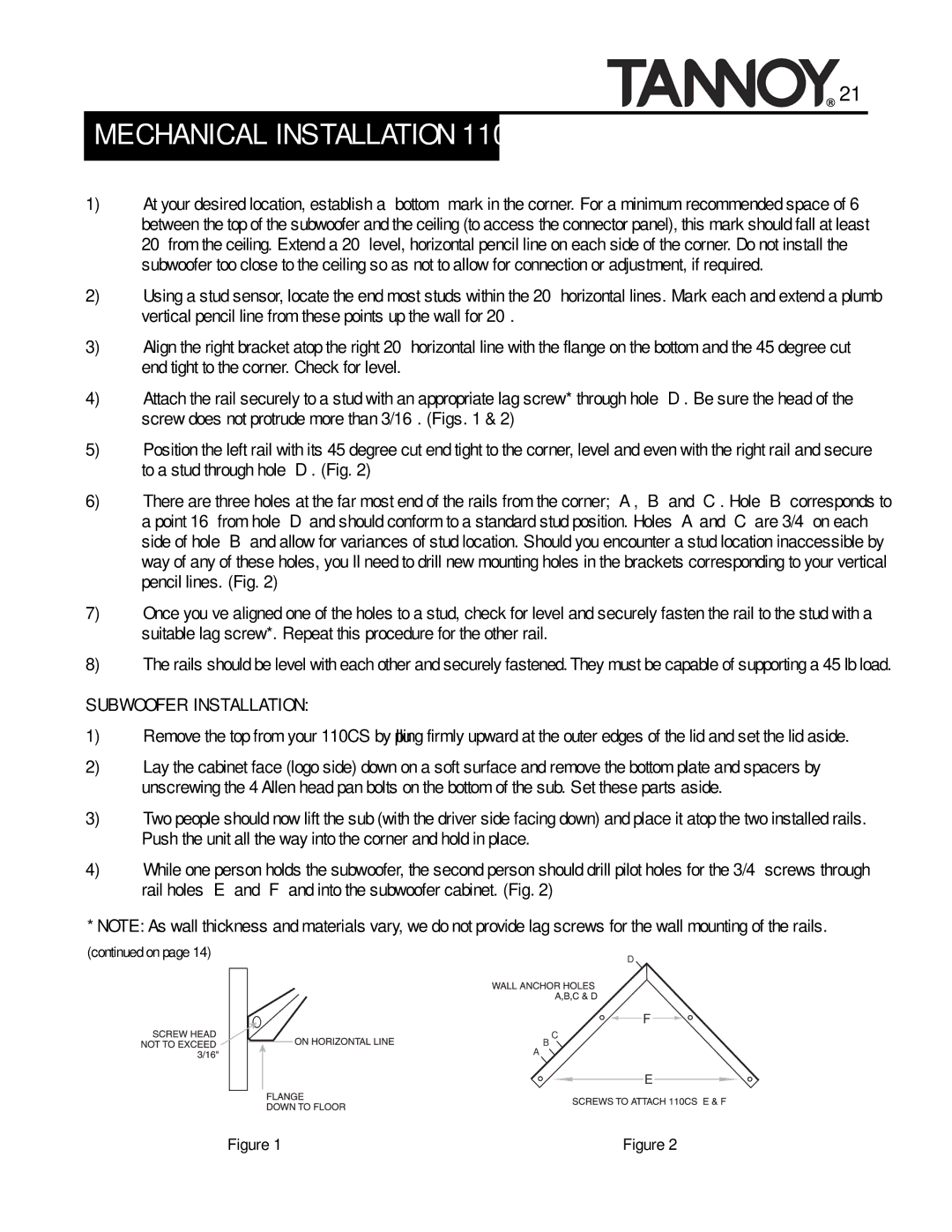
4)Attach the rail securely to a stud with an appropriate lag screw* through hole “D”. Be sure the head of the screw does not protrude more than 3/16”. (Figs. 1 & 2)
5)Position the left rail with its 45 degree cut end tight to the corner, level and even with the right rail and secure to a stud through hole “D”. (Fig. 2)
6)There are three holes at the far most end of the rails from the corner; “A”, “B” and “C”. Hole “B” corresponds to a point 16” from hole “D” and should conform to a standard stud position. Holes “A” and “C” are 3/4” on each side of hole “B” and allow for variances of stud location. Should you encounter a stud location inaccessible by way of any of these holes, you’ll need to drill new mounting holes in the brackets corresponding to your vertical pencil lines. (Fig. 2)
7)Once you’ve aligned one of the holes to a stud, check for level and securely fasten the rail to the stud with a suitable lag screw*. Repeat this procedure for the other rail.
8)The rails should be level with each other and securely fastened. They must be capable of supporting a 45 lb load.
SUBWOOFER INSTALLATION:
1)Remove the top from your 110CS by pulling firmly upward at the outer edges of the lid and set the lid aside.
2)Lay the cabinet face (logo side) down on a soft surface and remove the bottom plate and spacers by unscrewing the 4 Allen head pan bolts on the bottom of the sub. Set these parts aside.
3)Two people should now lift the sub (with the driver side facing down) and place it atop the two installed rails. Push the unit all the way into the corner and hold in place.
4)While one person holds the subwoofer, the second person should drill pilot holes for the 3/4” screws through rail holes “E” and “F” and into the subwoofer cabinet. (Fig. 2)
* NOTE: As wall thickness and materials vary, we do not provide lag screws for the wall mounting of the rails.
(continued on page 14) | D |
|
A
F
B C![]()
E
Figure 1 | Figure 2 |
