2 – Parts of the FW-1082
Front Panel
The
See “Control Surface Modes” on page 16 for details of these different modes and how to set them:
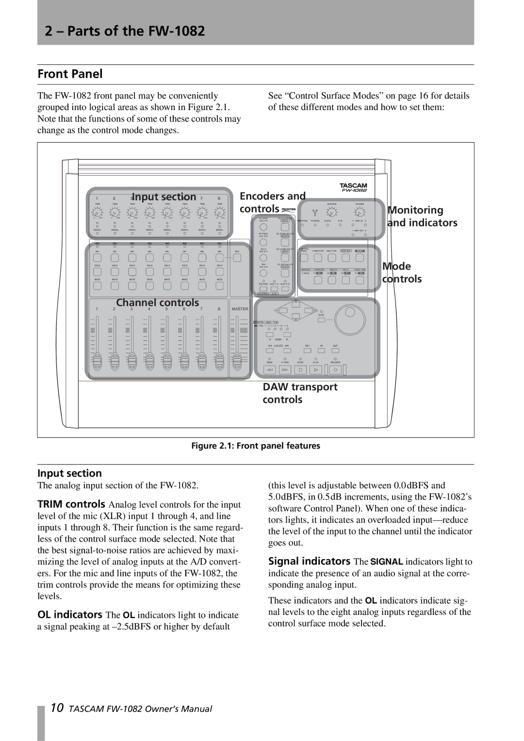
Input section | Encoders and |
|
| controls | Monitoring |
|
| and indicators |
|
| Mode |
|
| controls |
Channel controls |
|
|
| DAW transport |
|
| controls |
|
Figure 2.1: Front panel features
Input section
The analog input section of the
TRIM controls Analog level controls for the input level of the mic (XLR) input 1 through 4, and line inputs 1 through 8. Their function is the same regard- less of the control surface mode selected. Note that the best
OL indicators The OL indicators light to indicate a signal peaking at
(this level is adjustable between 0.0dBFS and
5.0dBFS, in 0.5dB increments, using the
Signal indicators The SIGNAL indicators light to indicate the presence of an audio signal at the corre- sponding analog input.
These indicators and the OL indicators indicate sig- nal levels to the eight analog inputs regardless of the control surface mode selected.
10 TASCAM