2102 Wireless Communication Module Section 2 Introduction
2.4Technical Specifications
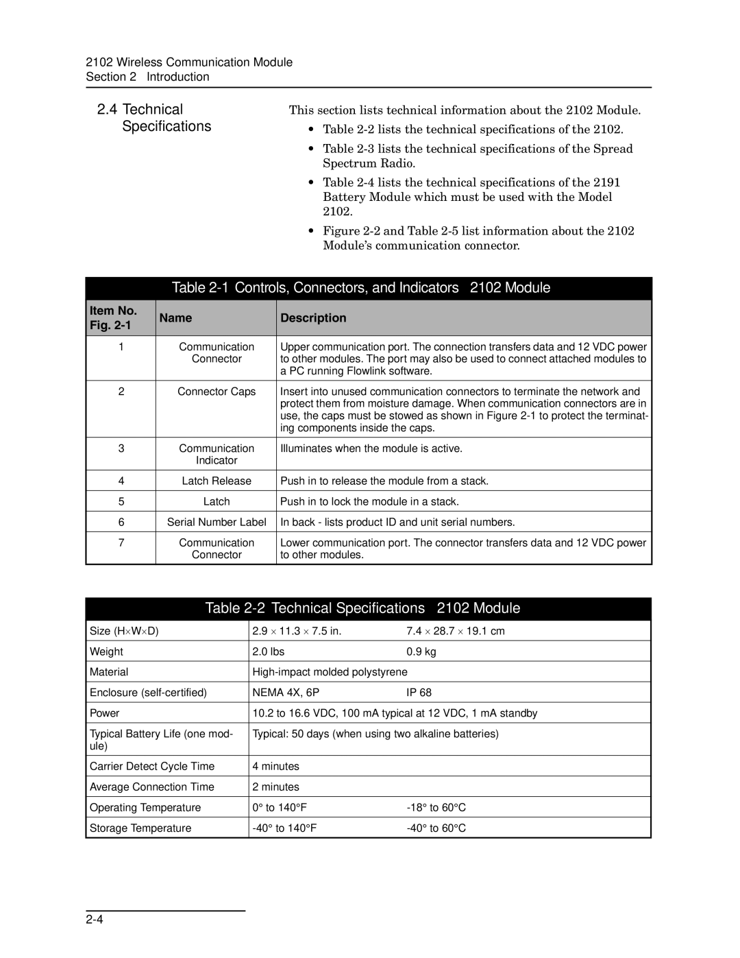
This section lists technical information about the 2102 Module.
•Table
•Table
•Table
•Figure 2-2 and Table 2-5 list information about the 2102 Module’s communication connector.
Table 2-1 Controls, Connectors, and Indicators – 2102 Module
Item No. | Name | Description | |
Fig. | |||
|
| ||
1 | Communication | Upper communication port. The connection transfers data and 12 VDC power | |
| Connector | to other modules. The port may also be used to connect attached modules to | |
|
| a PC running Flowlink software. | |
|
|
| |
2 | Connector Caps | Insert into unused communication connectors to terminate the network and | |
|
| protect them from moisture damage. When communication connectors are in | |
|
| use, the caps must be stowed as shown in Figure | |
|
| ing components inside the caps. | |
|
|
| |
3 | Communication | Illuminates when the module is active. | |
| Indicator |
| |
|
|
| |
4 | Latch Release | Push in to release the module from a stack. | |
|
|
| |
5 | Latch | Push in to lock the module in a stack. | |
|
|
| |
6 | Serial Number Label | In back - lists product ID and unit serial numbers. | |
|
|
| |
7 | Communication | Lower communication port. The connector transfers data and 12 VDC power | |
| Connector | to other modules. | |
|
|
|
Table 2-2 Technical Specifications – 2102 Module
Size (H⋅W⋅D) | 2.9 ⋅ 11.3 ⋅ 7.5 in. | 7.4 ⋅ 28.7 ⋅ 19.1 cm |
|
|
|
Weight | 2.0 lbs | 0.9 kg |
|
| |
Material | ||
|
|
|
Enclosure | NEMA 4X, 6P | IP 68 |
|
| |
Power | 10.2 to 16.6 VDC, 100 mA typical at 12 VDC, 1 mA standby | |
|
| |
Typical Battery Life (one mod- | Typical: 50 days (when using two alkaline batteries) | |
ule) |
|
|
|
|
|
Carrier Detect Cycle Time | 4 minutes |
|
|
|
|
Average Connection Time | 2 minutes |
|
|
|
|
Operating Temperature | 0° to 140°F | |
|
|
|
Storage Temperature | ||
|
|
|
