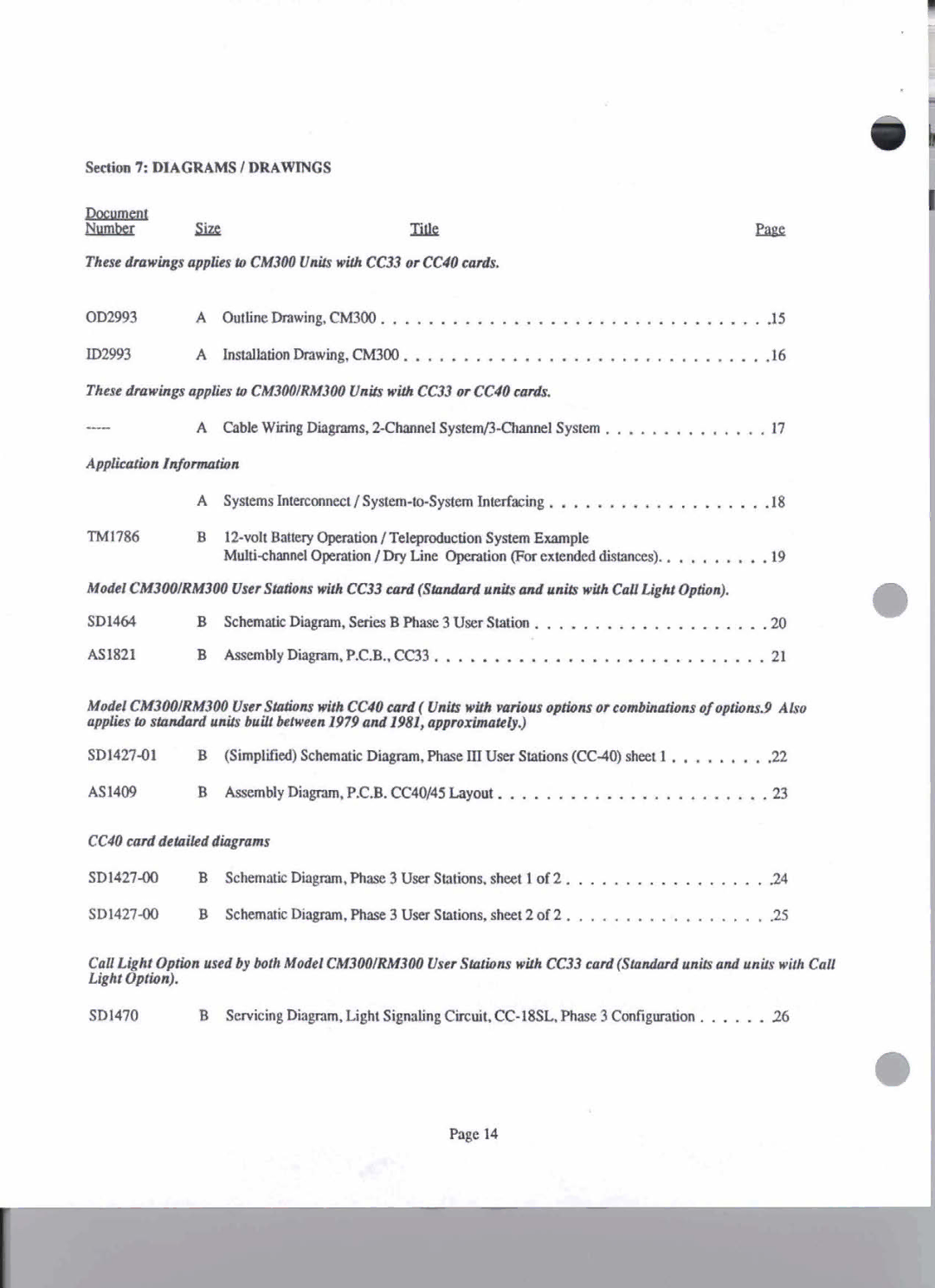
Sectim 7: DIAGRIMSI DRAWINGS
Dacumcnt
Nunbet
m
These dnnvingaapplies 0 CM300 Unifs with CC33 or CC40 wnlr.
OD2993 | A | Outlinehawin& CMU)O | |
ID2993 | A | Installationhawing. CM300 | .16 |
Thesednawingsapplicp & CM300lRM300Units with CC33 orCC40 d. |
| ||
- | A | Cable Wiring Diagrams,2Chwncl SystemM!ha~elSystem | 17 |
TM1786 | B |
|
| M u l t i c ~ O p e m t h I D ~ ~ L Opeaarim(?brextendeddistmas)n e | 19 |
Model CM3WIRM3W UserSOatOna with 1333Eonl (Slrudrml uni& and vnib with CdJLight Option).
SD1464 | B Schanatic Diagram, Scrim B Phase 3 User Statim | .20 |
AS1821 | B AssemblyDhgmm,P.C.B.,CC33. .. ..................... . . ..21 | |
Model CM3WIRM3W User SPllions with CC40cud( U& w&h wiow oprions or eombindonx of oprions9 Also applies tosPMdordunifs kill khveen 1979and198l, appr0xhakly.J
AS1409 B Assembly Diagram, P.C.B. CCW45Layout. ... . . ... .. ... .. ...... .23
CC40 antidetailedd i a g m |
| ||
| B | Schematic Digram, Phase3 User Stations, sheet 1 of 2 .. . | . . . . . . . . . . . 24 |
SD1427M) | B | SchemluicD i . P h a s e 3 Usa Stations, sheet 2 of 2 | . . . . . . . .. . .25 |
Cali L'8ht Option used by both Modal CM300IRM300 User S & ~ Mwith CC33 ccvd(Standard unitsand units with Call ~ i g h t plion).
SD1470 B ServicingDiagram, Light Signaling
Page 14
